Generac Power Systems PWRmanager Скачать руководство пользователя страница 9

Operation

Owner’s Manual for Generac PWRmanager 12 Relay Load Controller 

5

Section 3: Operation

Before using the PWRview app to manage circuits, the

PWRmanager must be wired, configured, and registered

by the installer.
Download the Generac PWRview app from Google Play

or the Apple App Store. Log in using the email the PWR

-

cell system is registered to. Follow the sections below to

configure automatic control, and to control loads directly

from the app.

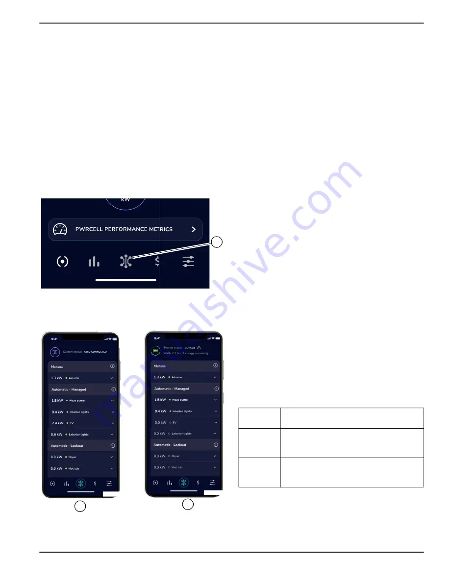
Circuits List Screen in PWRview 

Once the PWRmanager is registered, a new screen will

be added in the app. To view that screen, tap on the Cir

-

cuits List icon in the center of the navigation bar (A) See

Figure 3-1

. 

Figure 3-1. Circuits List Icon

There  are  several  elements  to  the  circuits  list  screen

described below.

Figure 3-2. Circuits List Screen

Power Source Header

See 

Figure  3-2

.  At  the  top  of  the  screen  in  (A),  the

header shows the grid icon which indicates that the sys

-

tem is grid connected.
When  in  an  outage  (B),  the  header  shows  the  battery

icon, state of charge, and an estimate for how long the

battery will last.

Circuit Groups

Loads wired to connect through the PWRmanager during

installation will appear in groups based on how they are

currently controlled.

Manual Group

See 

Figure 3-2

. Circuits configured as manual on or off

appear  at  the  top  of  the  list  below  the  power  source

header. If no circuits are manually controlled, this section

will not appear.

Automatic - Managed Group 

See 

Figure 3-2

. Prioritized circuits appear in the upper

group of the Circuits List screen: circuits at the top of this

section will be disabled last when available power capac

-

ity reduces.

Automatic - Lockout Group

Lockout Loads  appear in  the bottom  portion of  the  Cir

-

cuits  List  screen,  as  shown  in


Figure  3-2

.  These  are

shed  immediately  upon  entering  an  outage.  This  helps

conserve battery  energy  to  last through  longer  outages

and prevent overloading the PWRcell system.

System Status and Settings 

See 

Figure  3-3

.  When  scrolling  down to  the  bottom  of

the Circuits List screen, a button to bring up the system

status of the unit will appear. Tap on it to see the following

status information for the PWRmanager:

A

012946

012947

A

B

Internet

This indicates if the PWRmanager unit is

connected to the internet.

System

If an error has occurred in the PWRman

-

ager or a circuit error exists, it will be indi

-

cated here.

Switch 

Position

Shows the position of the Mode Selector

Knob.  If  it  isn’t  in  “Normal”,  the  system

will not function correctly.

Содержание PWRmanager

Страница 1: ...fe This product is not intended to be used in a critical life support application Failure to adhere to this warning could result in death or serious injury Register your Generac product at https pwrfl...

Страница 2: ...label on this page See Serial Number Location When contacting an Independent Authorized Service Dealer IASD or Generac Customer Service always supply the complete model number and serial number of the...

Страница 3: ...er 5 Circuit Groups 5 System Status and Settings 5 Navigation Bar 6 Controlling Loads in PWRview 6 Connecting to PWRmanager 7 Configuring PWRmanager 7 Configure Each Circuit 7 Add or Delete a Circuit...

Страница 4: ...iv Installation Manual for Generac PWRmanager 12 Relay Load Controller This page intentionally left blank...

Страница 5: ...it is safe for others and does not render the equipment unsafe Throughout this publication and on tags and decals affixed to the unit DANGER WARNING CAUTION and NOTE blocks are used to alert personne...

Страница 6: ...or serious injury 000209b WARNING Loss of life This product is not intended to be used in a critical life support application Failure to adhere to this warning could result in death or serious injury...

Страница 7: ...es a richly integrated load management functionality when used with the PWRcell system Whole Home Backup With whole home backup during an outage the main breaker panel will be disconnected from the ut...

Страница 8: ...losed or open See Troubleshooting for more information C Relay Pairing LEDs Off Relays not paired Green Relays are paired as 240 V circuit Red Relays are paired but at least one relay is not operating...

Страница 9: ...g installation will appear in groups based on how they are currently controlled Manual Group See Figure 3 2 Circuits configured as manual on or off appear at the top of the list below the power source...

Страница 10: ...It will show the current configuration for the circuit Tap one of the unselected radio buttons to change it The request will be executed and the panel will close Figure 3 6 Controlling Loads in PWRvi...

Страница 11: ...1 Open the mobile device s WiFi configuration tab find the PWRmanager xxxxx WiFi AP network and connect to it 2 Open a browser on the device and point it at the IP address http 10 10 10 10 to open th...

Страница 12: ...l last long enough during an extended outage This is the same as selecting Automatic Lock out in the PWRview app and will be modified by changes from the app Figure 3 10 Configuring Lockout Minimum Of...

Страница 13: ...ons for circuit connections Read below for important points to consider when select ing circuits Loads can be wired through PWRmanager for load management or can be wired directly without passing thro...

Страница 14: ...igured to run if they do not overload the inverter If the total load exceeds the power capacity of the inverter these will be shed in priority order to ensure the inverter continues to run Loads to co...

Страница 15: ...R Outdoor Mounting Description Value Dimensions excluding flange Width 14 in x Height 9 in x Depth 5 in 35 56 cm x 22 86 cm x 12 7 cm Weight 14 3 lb 6 5 kg Wire Sizes 14 through 6 AWG Description Valu...

Страница 16: ...Specifications 12 Owner s Manual for Generac PWRmanager 12 Relay Load Controller This page intentionally left blank...

Страница 17: ...the installer Pressing the reset button for 10 seconds will reset the unit to out of the box conditions NOTE This will require that all WiFi information be entered again and will cause all relay and l...

Страница 18: ...rload on the inverter from the unmanaged loads Turn off breakers on some unman aged loads as needed for inverter to continue to supply power All relays are on The web interface and app cannot change a...

Страница 19: ...or Generac PWRmanager 12 Relay Load Controller 15 Dimensions and Drawings Section 6 Dimensions and Drawings Enclosure Base 150 5 9 400 15 7 78 3 1 288 11 3 45 1 8 18 7 41 1 6 38 1 5 DIMENSIONS ARE IN...

Страница 20: ...16 Owner s Manual for Generac PWRmanager 12 Relay Load Controller Dimensions and Drawings This page intentionally left blank...

Страница 21: ...Owner s Manual for Generac PWRmanager 12 Relay Load Controller 17 Dimensions and Drawings This page intentionally left blank...

Страница 22: ...18 Owner s Manual for Generac PWRmanager 12 Relay Load Controller Dimensions and Drawings This page intentionally left blank...

Страница 23: ......

Страница 24: ...rights reserved Specifications are subject to change without notice No reproduction allowed in any form without prior written consent from Generac Power Systems Inc Generac Power Systems Inc S45 W2929...

Отзывы: