background image

Owner’s Manual for Generac PWRcell Inverter

19

Maintenance

Section 4: Maintenance

Service

The  PWRcell  inverter  must  be  serviced  by  a  qualified

technician.  See  the  Generac  PWRcell  Inverter

Installation  Manual  for  information  and  instructions  on

service and field-replaceable parts.
One  of  the  biggest  reducers  of  system  performance  is

dirty  solar  panels.  Generac  Power  Systems,  Inc.

recommends  solar  panels  be  cleaned  regularly  by  a

qualified  person  to  ensure  optimum  performance  and

maximum  energy  savings.  Contact  the  nearest

Independent  Authorized  Service  Dealer  (IASD),  your

system installer, or Generac Customer Service at 1-888-

436-3722 

(1-888-GENERAC), 

or 

visit

www.generac.com


for assistance.

Annual Maintenance

On an annual basis:

Clean the exterior of the enclosure with a soft cloth.

Ensure surrounding area is free of leaves, pet hair

or other debris that could obstruct airflow in or out

of the unit.

Inspect  the  unit.  Look  for  conditions  that  could

hinder  performance  or  safety,  such  as  (but  not

limited to): 
– Blocked vents
– Dirty intake filter
– Loose/missing hardware
– Loose or broken electrical connections.

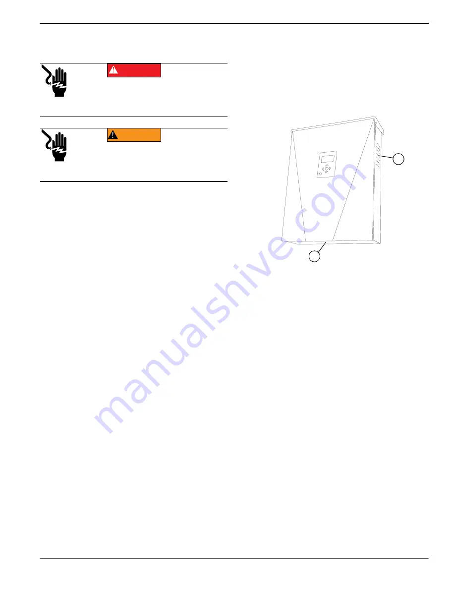
Inspecting Vents

See 

Figure 4-1

. Verify intake vent (A) and exhaust vent

(B) are clear at all times.

Cleaning Intake Filter

See 

Figure 4-1

. Clean intake filter (A) with a soft brush or

vacuum  cleaner.  If  air  filter  is  damaged  or  becomes

difficult  to  clean  contact  the  nearest  Independent

Authorized Service Dealer (IASD) or Generac Customer

Service  at  1-888-GENERAC  (1-888-436-3722)  or  visit

www.generac.com


for a replacement filter.

Figure 4-1. Intake Vent and Exhaust Vent

Recovery From an Error State

Error events will force the PWRcell inverter into an error

state  where  no  DC  power  is  exported,  though  voltage

may still be present on REbus from connected devices.

To  recover  a  device  from  an  error  state,  disable  then

enable  that  device.  See 

Enabling  and  Disabling

Devices

 for more information. 

If the system is unable to be accessed, but is connected

to the  Internet,  contact  the nearest  Independent Autho

-

rized Service Dealer (IASD) or Generac Customer Ser

-

vice  at  1-888-436-3722  (1-888-GENERAC),  or  visit

www.generac.com

 for assistance. 

Electrocution. Activate safety shutdown before 
performing emergency or service work. Failure 
to do so will result in death, serious injury, or 
equipment or property damage.

(000628a)

DANGER

Electrocution. Only an authorized technician should 
attempt to service this equipment. Failure to follow 
proper service requirements could result in death, 
serious injury, or equipment or property damage.

(000629b)

WARNING

A

B

0009890

Содержание PWRcell XVT076A03

Страница 1: ...life This product is not intended to be used in a critical life support application Failure to adhere to this warning could result in death or serious injury Register your Generac product at https pwrfleet generac com 1 888 GENERAC 888 436 3722 Para español visita http www generac com service support product support lookup Pour le français visiter http www generac com service support product suppo...

Страница 2: ...ge See Serial Number Locations When contacting an Independent Authorized Service Dealer IASD or Generac Customer Service always supply the complete model number and serial number of the unit Table 1 Generac PWRcell Inverter Important Information Unit Model Number Unit Serial Number Date Purchased Commissioning Date 000393a WARNING CANCER AND REPRODUCTIVE HARM www P65Warnings ca gov ...

Страница 3: ...ter LED 7 Internet LED 8 Shutdown Mode 8 System Modes Overview 8 Grid Tie 8 Clean Backup 9 Priority Backup 9 Self Supply 9 Self Supply Setpoints 10 Section 3 Operation 13 Operation and User Interface 13 Home Screen 13 Selecting System Modes 13 Device Pages 14 Enabling and Disabling Devices 14 Mod Settings Menu 15 Ethernet Configuration 17 Ethernet Setup 17 Serial Number and Registration 17 Other E...

Страница 4: ...iv Owner s Manual for Generac PWRcell Inverter This page intentionally left blank ...

Страница 5: ...on tags and decals affixed to the unit are not all inclusive If using a procedure work method or operating technique that the manufacturer does not spe cifically recommend verify that it is safe for others and does not render the equipment unsafe Throughout this publication and on tags and decals affixed to the unit DANGER WARNING CAUTION and NOTE blocks are used to alert personnel to special inst...

Страница 6: ...matic start up Disconnect utility power and render unit inoperable before working on unit Failure to do so will result in death or serious injury WARNING Risk of injury Do not operate or service this machine if not fully alert Fatigue can impair the ability to service this equipment and could result in death or serious injury 000215 000209b WARNING Loss of life This product is not intended to be u...

Страница 7: ...irst aid and get medical help Failure to do so will result in death or serious injury 000599 Electrocution Turn battery disconnect OFF and de energize REbus before touching terminals Failure to do so will result in death serious injury equipment and property damage DANGER 000152 DANGER Electrocution Verify electrical system is properly grounded before applying power Failure to do so will result in...

Страница 8: ...Introduction and Safety 4 Owner s Manual for Generac PWRCell Inverter This page intentionally left blank ...

Страница 9: ...ating AC 1 Operating voltage range AC XVT076A03 L N V rms 108 120 130 Operating voltage range AC XVT076A03 L L V rms 216 240 260 Operating voltage range AC XVT114G03 L N V rms 108 120 130 Operating output voltage range AC XVT114G03 L L V rms 184 208 228 Continuous output current AC grid tied A rms 32 PCS controlled current grid tied Arms 32 Continuous output current AC islanded A rms 42 Output fau...

Страница 10: ...wer PWRcell inverters disconnect from the grid and provide AC power to support protected loads when configured to do so All PWRcell products use the REbus 380 VDC nanogrid to connect to each other The REbus nanogrid automates the flow of power to enable plug and play setup and operation of PWRcell equipment For more information about REbus visit www generac com In Figure 2 3 PWRcell inverter E is ...

Страница 11: ...ific fault detected Inverter LED Inverter LED D communicates the status of the utility grid and or inverter through LED color and state Green utility is connected and within normal operational voltage and frequency Yellow utility grid is not within normal conditions and the inverter is in a waiting state User intervention typically is not required The inverter will restart as soon as the utility g...

Страница 12: ...Modes Overview Generac PWRcell offers several system modes for various installation configurations markets and applications Connected REbus devices work together to manage the distribution of power based on the selected system mode Some modes interact with PWRcell batteries to store power and or balance production and consumption See Table 2 1 and Table 2 2 for an overview of available system mode...

Страница 13: ...ar power is used to charge the battery When the available solar power is lower than the battery input power rating the inverter uses grid power to expedite battery charging See Figure 2 8 If solar and grid power are available both can charge the battery The system displays the amount of power being drawn from the grid and the amount of power being consumed by local loads before reaching the batter...

Страница 14: ... Self Supply mode only and are only used for specific applications See Table 2 3 Self Supply Setpoints 009962 009963 011241 Table 2 3 Self Supply Setpoints Setpoint Description Default Units TargMaxImprtP Target Maximum Import Power Maximum power imported from the grid at any point When the overall building load exceeds this setpoint the inverter will supply additional power from the battery and s...

Страница 15: ...information on CT calibration see the PWRcell Inverter Installation Manual NOTE This feature is NOT intended to serve as a means of achieving compliance to Utility interconnection requirements For information on export limiting settings related to Utility compliance see the PWRcell Inverter Installation Manual When enabled Export Override allows the user to restrict inverter export such that exces...

Страница 16: ...12 Owner s Manual for Generac PWRcell Inverter General Information This page intentionally left blank ...

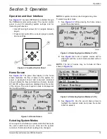
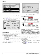
Страница 17: ...he current system mode is displayed at the top of the screen Figure 3 2 Home Screen Selecting System Modes Once a system is installed a system mode that best suits the user s needs must be set Once set the system remains in that mode without needing to be changed NOTE A system mode can be changed at any time To select a system mode 1 See Figure 3 3 While viewing the home screen press the center bu...

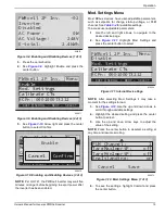
Страница 18: ... enabled by the user before the device will operate If a device is disabled the device will remain in a disabled state and will not resume operation until enabled by the user Once enabled if grid power is present the inverter will create DC voltage establishing the REbus nanogrid All devices connected to REbus will wake up and begin communications To enable a device 1 Use the right arrow key to sc...

Страница 19: ...r button to select Figure 3 11 Internet Device Page NOTE After selecting Mod Settings it may take a moment for the settings to load 3 See Figure 3 12 Use the up and down arrows to scroll through available settings 4 Highlight the desired setting and press the center button to select 5 Use the up and down arrow keys to adjust the value of the setting NOTE Press the center button to deselect a setti...

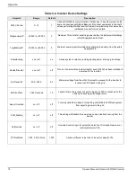
Страница 20: ...ding backup power during a grid outage EnaExtTransfer on or off off Turn on if an external automatic transfer switch ATS has been installed to operate with the Inverter ExtTransVolt 50 0 200 0 95 Minimum voltage from the utility that must be present for the inverter to reconnect an ATS back to the grid ExtTransTime 1 360 Seconds 15 Length of time the inverter will wait to trigger an ATS to reconne...

Страница 21: ...e can be monitored from the PWRview online monitoring system and mobile app To register a system for PWRview monitoring 1 See Figure 3 13 Locate the serial number and registration code on the registration decal on the front of the inverter This information will be required for registration 2 Navigate to https pwrfleet generac com or if using a mobile device scan the registration label QR code 3 Fo...

Страница 22: ...Operation 18 Owner s Manual for Generac PWRCell Inverter This page intentionally left blank ...

Страница 23: ...vent B are clear at all times Cleaning Intake Filter See Figure 4 1 Clean intake filter A with a soft brush or vacuum cleaner If air filter is damaged or becomes difficult to clean contact the nearest Independent Authorized Service Dealer IASD or Generac Customer Service at 1 888 GENERAC 1 888 436 3722 or visit www generac com for a replacement filter Figure 4 1 Intake Vent and Exhaust Vent Recove...

Страница 24: ...rights reserved Specifications are subject to change without notice No reproduction allowed in any form without prior written consent from Generac Power Systems Inc Generac Power Systems Inc S45 W29290 Hwy 59 Waukesha WI 53189 1 888 GENERAC 1 888 436 3722 www generac com ...

Отзывы: