Page 4
5.
System layout
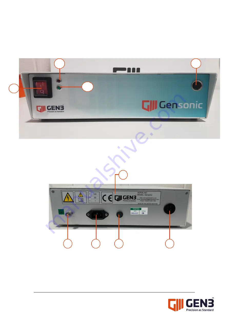
Front panel
1)
On/Off power switch
2)
Red LED illuminated indicates ultrasonic driver circuit is working correctly.
3)
Green LED illuminated indicates transducer head unit is operating.
4)
Output socket for hand held transducer head.
Back panel
1)
Earth point
2)
IEC Main power socket
3)
Fuse holder (1A or 2A fuse is used according to voltage applied)
4)
Unit Information sticker includes Serial Number, Voltage and Fuse rate
5)
Socket for foot switch. (The transducer head unit is ON, when latching on foot
switch)
1
2
2
2
3
4
2
5
1
2
3
4
Содержание Gensonic
Страница 1: ...Gensonic INSTRUCTION MANUAL Version 3 0 ...


