background image

<5>

iTRAX iPod MIXER CONSOLE
INTRODUCTION:

Congratulations on your purchase of a 

iTRAX iPod MIXER CONSOLE

. The

iTRAX

, aside from being stylish and easy-to-use, is a high quality DJ mixer

that can be used in a variety of settings. With proper care and maintenance,
your mixer will provide years of reliable performance.

FEATURES:

- Dual docking stations for Apple® iPod® digital music players
- USB port with dock switch allows library management via PC
- 2 Phono/Line convertible inputs for use with additional devices 
- Composite video output for use with photo/video-enabled iPod®
- 3-Band rotary EQ with gain and cut feature per channel
- ¼" (6.35mm) Mic input with 2-Band EQ controls
- Master and Record RCA outputs
- Input selection switches
- Cue section with CH1/CH2 cue fader
- User replaceable X-Fader
- Lightweight, slimline design for complete portability

CAUTIONS:

1. All operating instructions should be read before using this equipment. 
2. To reduce the risk of electrical shock, do not open the unit. There are

NO USER REPLACEABLE PARTS INSIDE

. Please refer servicing to a qual-

ified Gemini Sound Products service technician. In the USA: If you experi-
ence problems with this unit, please call 1 (732) 738-9003 for Gemini
Customer Service. Do not attempt to return this equipment to your dealer.
3. Do not expose this unit to direct sunlight or to a heat source such as a
radiator or stove. When operating, ensure that the unit has adequate ven-
tilation. 
4. This unit should be cleaned only with a damp cloth. Avoid solvents or
other cleaning detergents.
5. When moving this equipment, it should be placed in its original carton
and packaging. This will reduce the risk of damage during transit.
6. 

DO NOT EXPOSE THIS UNIT TO RAIN OR MOISTURE

.

7. 

DO NOT USE ANY SPRAY CLEANER OR LUBRICANT ON ANY CON-

TROLS OR SWITCHES

.

CONNECTIONS / SETUP:

1. 

P

OWER

S

WITCH

The 

P

OWER

S

WITCH

(20) turns the unit 

O

N

or 

O

FF

. Make

sure the switch is in the ‘

O

FF

’ position prior to making any connections.

2. 

AC I

NLET

(31)

The 

AC I

NLET

(31), located on the rear of the unit, is the

connector which accepts the 

AC A

DAPTER

(supplied) used to power the unit. 

3. 

P

HONO

/L

INE

I

NPUTS

(24, 27) and 

P

HONO

/L

INE

S

ELECTOR

S

WITCHES

(25, 28):

These inputs allow for the connection of a phono-level turntable or a line-

level device. If you are connecting a phono-level device, you must switch
the corresponding 

P

HONO

/L

INE

S

ELECTOR

S

WITCH

to the 

PH 

position. When

using a line-level device, such as a CD player, the corresponding

P

HONO

/L

INE

S

ELECTION

S

WITCH

must be set to the 

LN 

position. Note that if

the repsective 

P

HONO

/L

INE

S

ELECTION

S

WITCH

is not in the correct position,

it may result in inaudible or distorted sound.
4.

G

ROUND

T

ERMINAL

: When using turntables with the 

P

HONO

/L

INE

I

NPUTS

(24, 27), it will be necessary to connect the 

G

ROUND

T

ERMINAL

(26), to elim-

inate hum. With the Power 

O

FF

, Simply fasten the grounding fork (includ-

ed with the turntable’s Phono Cable) underneath of the 

G

ROUND

T

ERMINALS

(26) found on the rear of the mixer.
5. 

1/4” M

IC

I

NPUT

(11): This input is found on the face of the mixer, and is

used for connecting microphones that are terminated with a 1/4” connec-
tor. This input is controlled solely by the volume and EQ controls found
directly to the right of the jack. 

For more information about using these

controls, see the Functions section.

6. 

1/4” H

EADPHONE

O

UTPUT

(18): This output is used for connecting virtu-

aly any type of headphones with a 1/4” (6.35mm) terminal. 
7. 

C

OMPOSITE

V

IDEO

O

UTPUT

(21): For 

iPod #

2 (right side) 

only

, this allows

for video output from a Video or Photo enabled iPod. Note that video pro-
grams played back from an iPod may appear grainy when connected to a
monitor or TV, because of the resolution of the source file. 
8. 

RCA M

ASTER

O

UTPUTS

(22): These audio outputs carry unbalanced audio

signals from the Master bus of the mixer. The 

M

ASTER

V

OLUME

C

ONTROL

(19)

determines the level of audio which is sent to these outputs.
9. 

R

ECORD

RCA O

UTPUTS

(23): These outputs is best suited for connecting

a recording device, as it is not altered by the 

M

ASTER

V

OLUME

C

ONTROL

(19).

This is useful in a live setting when you are required to change the overall
volume of your output, but you do not want to change the level of audio
being fed to the recording device. If you are not using a recording device,
these outputs are capable of driving another amplifier or speaker system,
but the volume will have to be set independently from the 

M

ASTER

V

OLUME

C

ONTROL

(19).

10. 

iPod D

OCK

(1) and 

D

OCKING

C

RADLE

: In conjunction with the 

D

OCKING

C

RADLE

, the 

iPod D

OCK

(1) is where the iPod connects to the mixer for both

audio and charging capabilities. 
11. 

USB I

NPUT

(29): This port allows you to use your 

iTRAX

as a dock for

your iPods. Using a standard A-to-B type USB cable, connect the 

iTRAX

to

any personal computer. Upon inserting your iPod into the 

iPod D

OCK

(1),

it may be accessed via your PC, for the purpose of managing music collec-

tions. The iPod which is accessed through the 

USB I

NPUT

(29) is deter-

mined by the position of the 

iPod 1/iPod 2 USB S

ELECTOR

switch (30). If

there is an iPod connected to your PC via the USB Input (29), you must

eject it properly, and remove the USB cable prior to moving the position of

the iPod 1/iPod 2 USB Selector switch (30).  Once you have followed this

procedure, you may reconnect the USB cable and manage music on the

opposite iPod. Please note that if you plan on using multiple iPods in con-

junction with iTunes software, you should disable automatic updates 

first

to prevent iTunes from erasing your music during syncronization! Gemini

assumes no liability arising from the inability to configure iTunes properly!

FUNCTIONS:

1. 

M

IC

V

OLUME

(12): This rotary control alters the volume of the

Microphone that is plugged into the 

1/4” M

IC

I

NPUT

(11). 

2. 

M

IC

H

IGH

B

AND

EQ 

(14): This rotary control alters the amount of high

frequency that is applied to the Microphone. Turning the control clockwise

increases the high frequencies, while turning the control counterclockwise

decreases. In the middle position (the rotary control is detented here),

there is no change being made to the audio signal.
3.

M

IC

1 L

OW

B

AND

EQ 

(15): This rotary control alters the amount of low

frequency that is applied to the Microphone. Turning the control clockwise

increases the low frequencies, while turning the control counterclockwise

decreases. In the middle position (the rotary control is detented here),

there is no change being made to the audio signal.
4. 

I

NPUT

S

ELECTOR

S

WITCH

(2): Using these switches allows you to switch

between the iPod or external input device connected to either channel.
5. 

C

HANNEL

G

AIN

C

ONTROL

(3): These controls, found on each mixer chan-

nel, allow you to increase or decrease the volume of each channel. This is

useful for matching levels during mixing, or to make additional signal

boosts when the 

C

HANNEL

V

OLUME

F

ADERS

(7) do not provide enough. 

6. 

C

HANNEL

H

IGH

B

AND

EQ 

(4): This rotary control, found on each channel,

alters the amount of high frequency that is applied to the corresponding

channel. Turning the control clockwise increases the high frequencies,

while turning the control counterclockwise decreases. In the middle posi-

tion (the rotary control is detented here), there is no change being made

to the audio signal.
7. 

C

HANNEL

M

ID

B

AND

EQ 

(5): This rotary control, found on each channel,

alters the amount of midrange frequency that is applied to the correspon-

ding channel. Turning the control clockwise increases the midrange fre-

quencies, while turning the control counterclockwise decreases. In the

middle position (the rotary control is detented here), there is no change

being made to the audio signal.
8.

C

HANNEL

L

OW

B

AND

EQ 

(6): This rotary control, found on each channel,

alters the amount of low frequency that is applied to the corresponding

channel. Turning the control clockwise increases the low frequencies,

while turning the control counterclockwise decreases. In the middle posi-

tion (the rotary control is detented here), there is no change being made

to the audio signal.
9. 

C

HANNEL

CUE S

ELECTOR

(16): This fader allows you to select which

device you would like to preview through the headphones. When the fader

is all the way to the left, only Channel 1 will be heard through the head-

phones. When the fader is all the way to the right, only Channel 2 will be

heard through the headphones. When the fader is in the middle, an equal

mix of Channel 1 and Channel 2 will be heard through the headphones.

10. 

C

UE

V

OLUME

C

ONTROL

(17): This controls the volume of the 

H

EADPHONE

O

UTPUT

(18).

11. 

C

HANNEL

V

OLUME

F

ADER

(7): These controls, found on each channel,

allow you to control the amount of signal that is sent to the output of the

mixer.

12. 

M

ASTER

LED VU M

ETER

(8): This VU meter displays the level of the sig-

nal being output through the 

M

ASTER

O

UTPUTS

of the mixer. For optimal

sound, this should not 5dB on the meter.

13. 

M

ASTER

V

OLUME

C

ONTROL

(19): This rotary control determines the vol-

ume of the audio being sent out through the 

M

ASTER

O

UTPUTS

(22).

Содержание Mixing Console for iPod iTrax

Страница 1: ...rom the use of information or any error contained in this manual No part of this manual may be reproduced stored in a retrieval system or transmitted in any form or by any means electronic electrical mechanical optical chemical including pho tocopying and recording for any purpose without the express written permission of Gemini Sound Products Corp It is recommended that all maintenance and servic...

Страница 2: ... by items placed upon or against them paying particular attention to cords at plugs convenience receptacles and the point where they exit from the product OUTDOOR ANTENNA GROUNDING If an outside antenna or cable sys tem is connected to the product be sure the antenna or cable system is grounded so as to provide some protection against voltage surges and built up static charges Article 810 of the N...

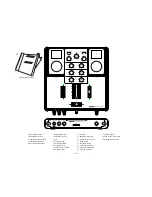
Страница 3: ...radle Adapters Manual with Warranty Info 1 iPod Dock 2 Input Selector Switch 3 Channel Gain Control 4 Channel High EQ Control 5 Channel Mid EQ Control 6 Channel Low EQ Control 7 Channel Volume Fader 8 LED VU Meters 9 X Fader 10 iPod Cradle Adapters 11 1 4 Mic Input 12 Mic Volume 13 Mic On Off Indicator LED 14 Mic High EQ Control 15 Mic Low EQ Control 16 Cue Selection Fader 17 Cue Volume Control 18...

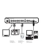
Страница 4: ...23 Record RCA Outputs 24 Phono Line Input 2 25 Phono Line 2 Selector Switch 26 Ground Terminal 27 Phono Line Input 1 28 Phono Line 1 Selector Switch 29 USB Input 30 iPod 1 iPod 2 USB Selector 31 AC Inlet Television or monitor w composite video input PA or Stereo System CD Player Turntable Personal Computer 4 ...

Страница 5: ... independently from the MASTER VOLUME CONTROL 19 10 iPod DOCK 1 and DOCKING CRADLE In conjunction with the DOCKING CRADLE the iPod DOCK 1 is where the iPod connects to the mixer for both audio and charging capabilities 11 USB INPUT 29 This port allows you to use your iTRAX as a dock for your iPods Using a standard A to B type USB cable connect the iTRAX to any personal computer Upon inserting your...

Страница 6: ...utputs Master RCA 0 dB 1V 400 Ohm Max 20V Peak to Peak Record 225 mV 5 KOhm Video Output Type RCA Composite General Frequency Response 20Hz 20KHz 2 dB Distortion 0 02 S N Ratio Better Than 80 dB Headphone Impedance 16 Ohm Power Source Adapter 115v 60Hz 15v AC 1 5A Adapter 230v 50Hz 15v AC 1 5A WEIGHTS AND DIMENSIONS Dimensions 12 5 x 4 2 x 14 318 x 107 x 356 mm Unit Weight 12 lbs 5 44 kg Specifica...

Страница 7: ... darauf stehenden oder gegen sie stoßenden Gegenständen gequetscht werden Achten Sie beson ders auf Kanten Sicherung Stecker und Buchsen AUSSENANTENNENERDUNG Wenn Sie eine Außenantenne oder ein Radio Fernsehkabelsignal an das Produkt anschließen achten Sie darauf dass die Antenne oder das Kabel geerdet sind um dafür zu sorgen dass Überspannungen und elektrostatische Aufladungen nicht auftreten kön...

Страница 8: ...ienungsanleitung mit Garantieinformation 1 iPod Dock 2 Eingangswahlschalter 3 Gain Regler 4 Equalizer Höhenregler 5 Equalizer Mittenregler 6 Equalizer Bassregler 7 Kanal Fader 8 LED VU Anzeige 9 Crossfader 10 iPod Ladestationadapter 11 6 3 mm Klinkenmikrofon eingang 12 Mikrofon Lautstärkeregler 13 Mikrofon Ein Aus Anzeige 14 Mic Equalizer Höhenregler 15 Mic Equalizer Bassregler 16 Cue Fader 17 Cue...

Страница 9: ...ecord Cinch Ausgänge 24 Phono Line Eingang 2 25 Phono Line 2 Wahlschalter 26 Erdungsanschluss 27 Phono Line Eingang 1 28 Phono Line 1 Wahlschalter 29 USB Eingang 30 iPod 1 iPod 2 USB Wahlschalter 31 Netzbuchse Fernsehgerät oder Monitor mit Composite Video Eingang PA oder Stereo Lautsprecher CD Player Plattenspieler Computer ...

Страница 10: ... da sie nicht vom MASTER VOLUME REGLER 19 beeinflusst werden Das ist sehr nützlich da Sie so während einer Live Performance die Lautstärke der Master Ausgänge ändern können ohne dass das mit aufgenommen wird Wenn die Ausgänge nicht für Aufnahmen verwendet werden können Sie daran auch einen weiteren Verstärker oder Lautsprecher anschließen Sie müssen die Lautstärke dafür jedoch separat einstellen 1...

Страница 11: ... 146 710 iPod MINI LADESTATIONADAPTER 003 810 iPod NANO LADESTATIONADAPTER 003 809 iPod VIDEO LADESTATIONADAPTER 003 808 iPod 1 2 UND 3 GENERATION LADESTATIONADAPTER 003 808 TECHNISCHE DATEN Eingänge Phono 3 mV 47 KOhm Line 150 mV 27 KOhm MIC 1 5 mV 1 K Ohm symmetrisch MIC High 12 dB MIC Low 12 dB USB Eingang USB 2 0 1 1 1 0 B Typ Ausgänge Master Cinch 0 dB 1 V 400 Ohm Max 20 V Spitze Spitze Recor...

Страница 12: ...pinche los mismos poniendo particular atención en la unión con el conector y en el punto donde se une a la unidad TOMA DE TIERRA DE ANTENA EXTERIOR Si hay conectado a este pro ducto un cable de antena o antena exterior asegúrese de su correcta conexión a tierra para proteger de posibles entradas de tensión y cargas de electricidad estática El Articulo 810 del Código Eléctrico Nacional ANSI NFPA 70...

Страница 13: ...iPod Manual Información con Garantia 1 Enclave iPod 2 Interruptor SelecciónEntrada 3 Control Ganancia Canal 4 Control EQ Canal Agudos 5 Control EQ Canal Medios 6 Control EQ Canal Graves 7 Fader Volumen Canal 8 Contadores LED VU 9 X Fader 10 Adaptadores Plataforma iPod 11 Entrada Micrófono jack 1 4 12 Volumen Micrófono 13 LED Indicador On Off Mic 14 Control Mic EQ Agudos 15 Control Mic EQ Graves 16...

Страница 14: ...ter 23 Salidas RCA Grabación 24 Entrada 2 Phono Line 25 Selector Phono Line 2 26 Terminal de Masa 27 Entrada 1 Phono Line 28 Selector Phono Line 1 29 Entrada USB 30 Selector USB iPod 1 iPod 2 31 Entrada corriente AC Television o monitor con entrada de video Sistema Estéreo o PA Lector CD Giradiscos Computador Personal ...

Страница 15: ...den utilizarse para dirigir señal hacia el amplificador o el sistema de altavoces pero el volumen funcionará independientemente del CONTROL DE VOLUMEN MASTER 19 10 ENCLAVE iPod 1 y ADAPTADOR DE ENCLAVE En conjunción con el ADAPTADOR DE ENCLAVE el ENCLAVE iPod 1 es donde cualquier iPod se conecta con el mezclador tanto alimentarlo como para audio 11 ENTRADA USB 29 Este puerto permite usar su iTRAX ...

Страница 16: ...RA iPod VIDEO 003 808 ADAPTADOR PARA iPod 1º 2º 3º GENERACIÓN 003 808 ESPECIFICACIONES Entradas Phono 3 mV 47 KOhm Linea 150 mV 27 KOhm MIC 1 5 mV 1 K Ohm Balanceada MIC Agudos 12dB MIC Graves 12dB Entrada USB USB 2 0 1 1 1 0 Tipo B Salidas Master RCA 0 dB 1V 400 Ohm Max 20V de Pico Grabación 225 mV 5 KOhm Salida Tipo Video RCA Compuesto General Respuesta en Frecuencia 20Hz 20KHz 2 dB Distorsión m...

Страница 17: ... Les cordons d alimen tation doivent être déroulés et rangés proprement afin d éviter de se pren dre les pieds dedans en particulier les cordons reliés aux prises élec triques ANTENNE EXTERIEURE Si vous reliez votre appareil à une antenne ou un câble extérieur assurez vous de la présence d une connexion à la terre afin d éviter les surtensions et les décharges d électricité statique L article 810 ...

Страница 18: ...ent pour iPod 4 x Adaptateur pour iPod Mode d emploi Garantie 1 Emplacement iPod 2 Sélecteur de source 3 Gain 4 Correction Aigu 5 Correction Médium 6 Correction Grave 7 Fader de Voie Volume 8 VU Mètre à LEDs 9 Crossfader 10 Adaptateur pour iPod 11 Prise Micro Jack 6 35mm 12 Volume Micro 13 LED Micro On Off 14 Correction Aigu Micro 15 Correction Grave Micro 16 Sélection Pré écoute 17 Volume Casque ...

Страница 19: ...ortie Enregistrement RCA 24 Entrée 2 Phono Ligne 25 Commutateur Phono Ligne 2 26 Borne de Masse 27 Entrée 1 Phono Ligne 28 Commutateur Phono Ligne 1 29 Port USB 30 Sélecteur US iPod 1 iPod 2 31 Embase pour alimentation AC TV ou moniteur avec entrée signal vidéo composite Système audio stéréo Lecteur CD Platine vinyle PC ...

Страница 20: ...seulement est équipé d une sortie vidéo permettant la diffusion de vidéo ou de photo en provenance d un baladeur iPod Notez que la qualité de ce type de programme provenant d un iPod peut être de qualité moyenne lorsque l appareil est connecté à un moniteur ou une TV Ceci est lié à la résolution du fichier source 8 SORTIE MASTER RCA 22 Il s agît de la sortie audio principale Asymétrique de la cons...

Страница 21: ...Sortie Principale Master RCA 0 dB 1V 400 Ohms Max 20V Crête Crête Sortie Enregistrement 225 mV 5 KOhms Sortie Video RCA Composite Générales Bande Passante 20Hz 20KHz 2 dB Distorsion 0 02 Rapport Signal Bruit 80 dB Impédance Casque 16 Ohms Alimentation Transformateur Externe 115v 60Hz 15v AC 1 5A Transformateur Externe 230v 50Hz 15v AC 1 5A POIDS DIMENSIONS Dimensions 12 5 x 4 2 x 14 318 x 107 x 35...

Страница 22: ...irst Name Last Name Province Address Number and Street City Apt Country Postal Code Model Number Example CDT 05 Serial Number Located on back of most units Serial Number Located on back of most units Month Day Year Date of Purchase Month Day Year Date of Purchase Purchase Price 00 EXCLUDING TAX Dealer Zip Code Age City or Month Day Year Date of Birth Model Number Example CDT 05 Save postage and re...

Отзывы: