


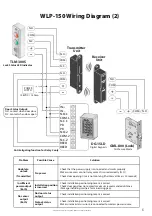

12 VDC
Copyright © All Rights Reserved. P-MU-WLP-150 Published: 2021.03.10
4
INPUT
Transmitter
Unit
12VDC
OUTPUT
Receiver
Unit
13.8VDC/1.5Amp
Ground
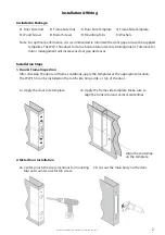
3e. For the door side unit, drill a wiring
channel to the electrified device to
be powered.
5. Frame Installation
For the frame side unit, repeat steps 2 or 3 to install on a metal or wood frame.
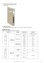
Wiring Instructions
Please refer to the wiring diagrams on page 5, 6.
WLP-150
Pigtail
Wire Color
Function
Frame
Door Leaf
Input Power
Reed Switch
Relay Output
(Lock Status)
Lock Status
Input
Lock Power
Output
Red (+)
Black (-)
Red
Black
White
Yellow
Blue
Green
Blue
Green
Red (+)
Black (-)
(Transmitter)
(Receiver)
N.C.
COM.
COM.
N.O.
N.C.
COM.
N.O.
N.O.