


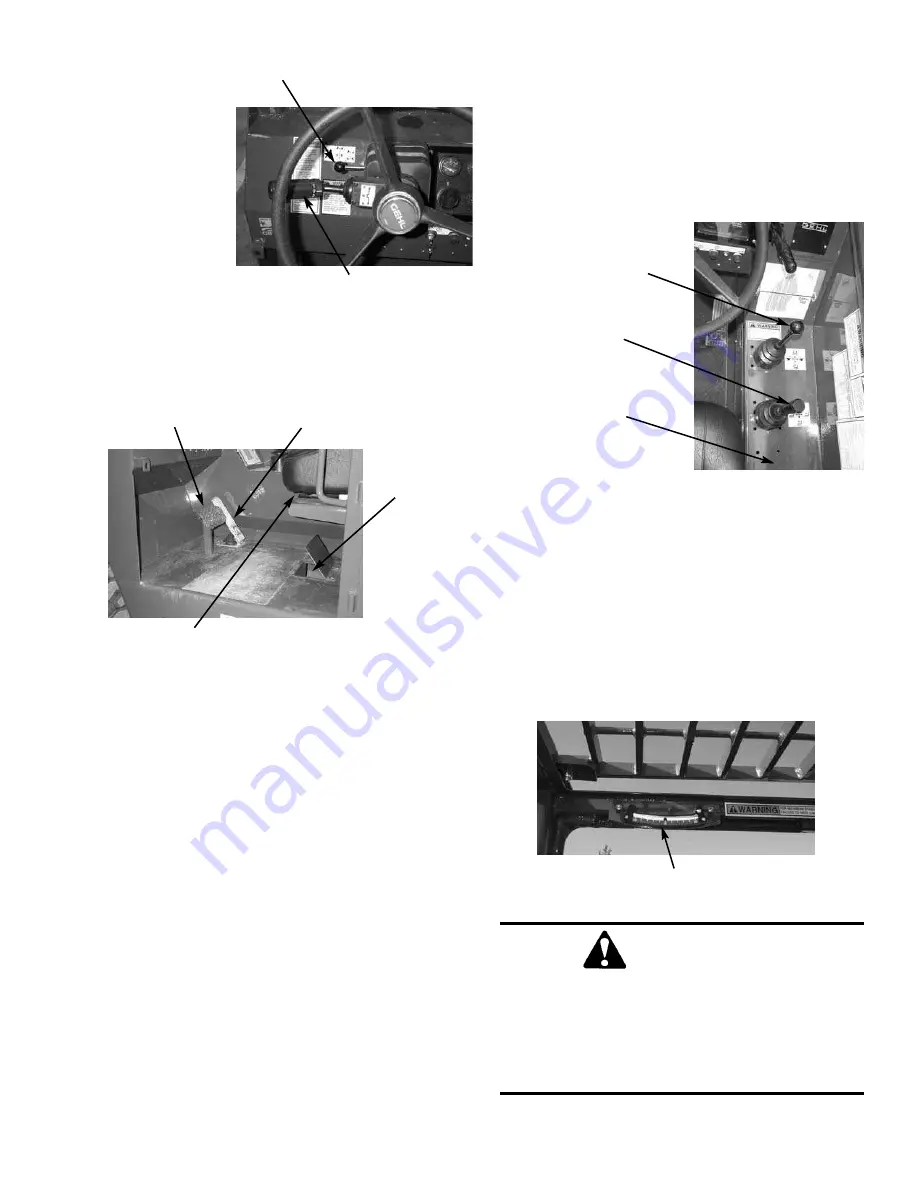
FLOOR AND SEAT AREA
Throttle Pedal:
This is right-foot operated and con-
trols the engine RPM to match increased power
requirements. Pushing down on the pedal increases the
RPM. Letting up on the pedal decreases RPM.
Service Brake Pedal:
Depressing this pedal activates
inboard hydraulic wet disc-type brakes on all four
wheels. Seperate front and rear brake systems allows
brake power to bring the machine to a safe stop, should
either system lose pressure.
Seat Positioning:
The seat is mounted on rails for for-
ward or backward repositioning to accommodate oper-
ator’s size and comfort. A spring-loaded latch handle
under the front of the seat activates the adjustment
mechanism.
Suspension Seat Option:
Option is available for addi-
tional operator comfort. It is adjustable for a soft or
firm ride.
Brake Fluid Reservoirs:
Lift hinged cover located on
the cab floor.
RIGHT SIDE PANEL
These controls and indicators are used to position the
frame, boom, and attachment. Graphic symbols on the
side panel illustrate the control actions.
Frame Level/Tilt Joystick:
The machine may be tilt-
ed slowly 10
o
to the left or right to level the frame and
boom in relation to the ground. Move the joystick han-
dle to the left to level the frame to the left. Move the
joystick handle to the right to level the frame to the
right.
Bubble Indicator:
Located in front of the operator on
the ROPS upper cross tube. Movement of the bubble
shows when the frame is level relative to sloping
ground surface.
PRINTED IN U.S.A.
25
908424/AP500
WARNING
DO NOT level the frame with the boom raised
or extended. Only level the machine while
stopped with the boom fully retracted and the
attachment raised just enough to clear the
ground.
THROTTLE
PEDAL
BRAKE
PEDAL
SEAT
POSITION
BRAKE
FLUID
BUBBLE INDICATOR
BOOM
JOYSTICK
FRAME LEVEL and
ATTACHMENT TILT
JOYSTICK
OPTION
JOYSTICK
(not shown)
STEERING WHEEL ADJUSTMENT
(later models)
SPEED SELECTOR
(later models)
Содержание Dynalift 552
Страница 1: ...Form No 908424 OPERATOR S MANUAL 552 553 Dynalift Telescopic Boom Forklift Courtesy of Crane Market...
Страница 8: ...INTENTIONALLY BLANK PAGE 908424 AP500 6 PRINTED IN U S A Courtesy of Crane Market...
Страница 10: ...INTENTIONALLY BLANK To be removed as Dealer s file copy 908424 AP500 8 Printed In USA Courtesy of Crane Market...
Страница 17: ...PRINTED IN U S A 15 908424 AP500 INTENTIONALLY BLANK Courtesy of Crane Market...
Страница 18: ...908424 AP500 16 PRINTED IN U S A L65928 SAFETY L65948 L65929 L66042 093475 Courtesy of Crane Market...
Страница 19: ...PRINTED IN U S A 17 908424 AP500 SAFETY L65925 L65440 L63690 L65925 L65925 Courtesy of Crane Market...
Страница 20: ...908424 AP500 18 PRINTED IN U S A SAFETY L65924 L65927 L65933 L65928 072798 Courtesy of Crane Market...
Страница 21: ...PRINTED IN U S A 19 9084241 AP500 SAFETY L65942 L65927 L65925 L65932 L65927 L65924 Courtesy of Crane Market...
Страница 22: ...908424 AP500 20 PRINTED IN U S A SAFETY Truss Boom Rotate Carriage L65927 L66042 Courtesy of Crane Market...
Страница 65: ...PRINTED IN U S A 63 908424 AP500 Date Hours Service Procedure MAINTENANCE LOG Courtesy of Crane Market...
Страница 69: ...Notes PRINTED IN U S A 67 908424 AP500 Courtesy of Crane Market...
Страница 70: ...552 553 Electrical Schematic J D Engine 908424 AP500 68 PRINTED IN U S A Courtesy of Crane Market...
Страница 71: ...552 553 Electrical Schematic Perkins Engine PRINTED IN U S A 69 908424 AP500 Courtesy of Crane Market...
Страница 72: ...552 553 Hydraulic Schematic 908424 AP500 70 PRINTED IN U S A A Courtesy of Crane Market...
Страница 73: ...552 553 Hydraulic Schematic PRINTED IN U S A 71 908424 AP500 A Courtesy of Crane Market...
Страница 77: ...553 L68675 Winch Boom Load Zone Charts PRINTED IN U S A 75 908424 AP500 Courtesy of Crane Market...
Страница 78: ...908424 AP500 76 PRINTED IN U S A Intentionally Blank Courtesy of Crane Market...


