


6 • ALARMS
time
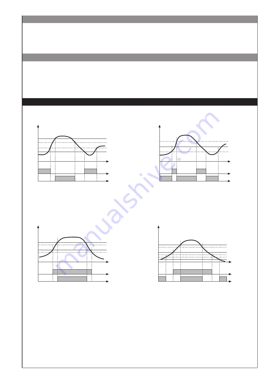
AL1 + H1
AL2 + H2
AL2
AL1
alarm 1
alarm 2
(*)
For AL1 inverse absolute alarm (min.) with positive H1, 1 t = 1
(*) = OFF if disabling on power-on exists
For AL2 direct absolute alarm (max) with negative H2, 2 t = 0
For AL1 inverse absolute, symmetrical alarm with hysteresis H1, 1 t = 5
For AL1 direct absolute, symmetrical alarm with hysteresis H1, 1 t = 4
Normal absolute alarm
Symmetrical absolute alarm
inverse
direct
AL1
AL1 + [ H1 ]
AL1 - [ H1 ]
time
For AL1 direct absolute alarm (max) with negative H 1, 1 t = 0
For AL2 direct relative alarm (max) with negative H2, 2 t = 2
For AL1 direct absolute alarm (max) with negative H1, 1 t = 0
For AL2 symmetrical deviation alarm H2, 2 t = 6
time
AL1+AL2
AL1
alarm 1
alarm 2
AL1+AL2
AL1
alarm 1
alarm 2
time
AL1 + AL2 + H2
Normal deviation alarm
(AL1 absolute, AL2 relative)
Symmetrical deviation alarm
(AL1 absolute, AL2 relative)
AL1-AL2
AL1 + H1
AL1+AL2+H2
AL1+H1
The input value and alarms are frozen while the logic input is active.
With the logic input active, a reset turns OFF both the relay outputs and the alarms latch.
Input value is sampled; state of alarms is not transferred to outputs; outputs are “frozen”.
When the logic input is active the input value is “frozen” and the outputs are updated according to the calculated alarms
state, including the ones latched.
• HOLD function
• FLASH function
5
81671B_MHW_40F96_0308_ENG