background image

• Protection

Protection code

Value

Displayed

Modifiable

parameters

parameters

0

o.1, o.2, o.3

o.1, o.2, o.3

1

o.1, o.2

o.1, o.2

2

o.1

o.1

3

o.1

none

+4 to disable In and Ou pages
+8 to disable Cf page
+16 to enable maintenance of reset memory at shutdown
+32 base configuration (the following parameters will not be displayed:

In: Ft, Fd, Of, L_L, H_L
Ou: On [forced to no. outputs present], rE)

P r

.......

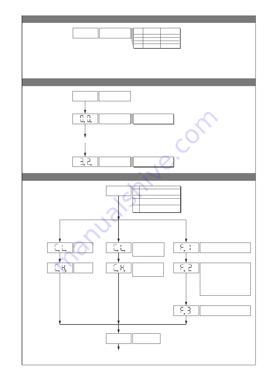
• Custom Linearization

Custom Linearization of

main input

Step 0

(beginning of scale value)

Display limits

(-1999 to 9999 for 4 digit display)

Step 32

(full scale value)

Display limits

(-1999 to 9999 for 4 digit display)

L n

the step value corresponds to input:

mV beginning scale + n * 

mV

mV = (mV full scale - mV beginning scale) / 32

• User Calibration

U.C. 

CPU B function

1

analog retransmission

output

2

potentiometer

3

strain-gauge

positive polarization

4

strain-gauge

symmetrical polarization

U. C.

Minimum

calibration (*)

Maximum

calibration (*)

(*) Press keys

∆ ∇

to

calibrate the analog
output

if U.C. = 1

Zero acquisition phase,
potentiometer with cursor
in minimum voltage
position

Maximum acquisition
phase, potentiometer
with cursor in maximum
voltage position

if U.C. = 2

if U.C. = 3, 4

Tare zero acquisition phase with strain-
gauge discharged (no weight or
pressure)

Acquisition phase for automatic definition
of sensitivity and full scale, load strain-
gauge with sample reference or
automatic activation of configured output
to check 6-lead sensor (only for version
SW 2.0x)
. 80% f.s. is set as default. The
value can be changed to set the value in
engineering units corresponding to the
sample used.

Zero recalculation phase, unload strain-
gauge by removing sample reference.

P.V.

Process variable

(LEVEL 1)

.......

enabled only if t.P = Linear Custom (only for version SW.2.0x)

Note: between the calibration phases some seconds could be requested to elaborate data.

5

81651C_MHW_40B48-96_0308_ENG

Содержание 40B 48

Страница 1: ...ming to these instructions 2 TECHNICAL SPECIFICATIONS FUNCTION CABLE LENGTH USED Input 1 mm2 3 m Power supply cable 1 mm2 1 m Relay output cables 1 mm2 3 5 m EMC conformity has been tested with the following connections 40B 48 40B 96 POSITION FORCE and PRESSURE INDICATOR INTERCEPTOR with INPUT for STRAIN GAUGE and POTENTIOMETER SOFTWARE VERSION 1 0x 2 0x code 81651C edition 09 03 08 USER S MANUAL ...

Страница 2: ... of output states OUT 1 Alarm 1 OUT 2 Alarm 2 OUT 3 Alarm 3 11 4 5 10 8 3 9 7 2 6 1 12 19 18 13 15 20 14 16 21 17 22 Standard 100 to 240Vac 10 Optional 20 to 27Vac dc 10 50 60Hz Power supply 23 24 PWR Label with engineering units Outputs Generic user configurable outputs relay 5A 250Vac logic 6V 20mA Rout 220Ω 19 21 20 22 Out2 Out1 4 CONNECTIONS Digital input 1500V isolation 1500V Ri 5 6KΩ 24V 4mA...

Страница 3: ... 2 Hysteresis parameters 999 999 scale points 999 999 scale points Hysteresis for set point 3 F Pressed for approx 2 sec Keep the F key pressed to browse the menus Release the F key to enter the displayed menu Press the F key to access the parameters Keep the F key pressed to exit any menu at any time S1 A B S5 S1 Status of Out 3 relay A Direct B Inverse S5 ON with digital input CPU BOARD CPU BOAR...

Страница 4: ...played if associated with at least one output Fault action in case of damaged sensor Er br Eb Value Output 1 Output 2 Output 3 0 OFF OFF OFF 1 ON OFF OFF 2 OFF ON OFF 3 ON ON OFF 4 OFF OFF ON 5 ON OFF ON 6 OFF ON ON 7 ON ON ON Output filter mode 0 not active calculated status is sent directly to relay 1 On delay DON 2 delay in activation of output after output is turned off DBI 3 Off delay DOF 4 D...

Страница 5: ...ization 4 strain gauge symmetrical polarization U C Minimum calibration Maximum calibration Press keys to calibrate the analog output if U C 1 Zero acquisition phase potentiometer with cursor in minimum voltage position Maximum acquisition phase potentiometer with cursor in maximum voltage position if U C 2 if U C 3 4 Tare zero acquisition phase with strain gauge discharged no weight or pressure A...

Страница 6: ...sis H1 1 t 4 Normal absolute alarm Symmetrical absolute alarm inverse direct AL1 AL1 H1 AL1 H1 time For AL1 direct absolute alarm max with negative H 1 1 t 0 For AL2 direct relative alarm max with negative H2 2 t 2 For AL1 direct absolute alarm max with negative H1 1 t 0 For AL2 symmetrical deviation alarm H2 2 t 6 time AL1 AL2 AL1 alarm 1 alarm 2 AL1 AL2 AL1 alarm 1 alarm 2 time AL1 AL2 H2 Normal...

Страница 7: ...e U C 3 Phase F1 unload the cell equal to applying input voltage of 0mV Wait 2 seconds for the signal to stabilize Press key F Phase F2 load the cell with a sample weight for example 80 of total weight equal to applying input voltage of 80 of 20mV 2mV 10V 16mV On display set a value equal to 80 of H S 800 Press key F Phase F3 unload the cell equal to applying input voltage of 0mV Wait 2 seconds fo...

Страница 8: ...ply should not be used to power relays contactors solenoid valves etc if the voltage waveform is strongly distorted by thyristor switching units or by electric motors it is recommended that an isolation transformer be used only for the devices connecting the screen to ground it is important for the electrical system to have a good ground connection voltage between neutral and ground must not excee...

Отзывы: