background image

39

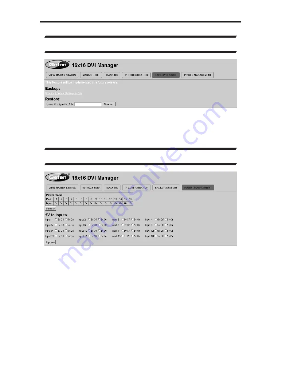
IP CONTROL - BACKUP/RESTORE & POWER MANAGEMENT

BACKUP/RESTORE

The 

Backup/Restore 

page is used to backup and restore complete setup 

configurations.

Note: 

 This feature will be implemented in a future release.

POWER MANAGEMENT

The 

Power Management 

page is used to set op5V power on an input to 

power specific optional devices. The current status of this feature for each input 

can be viewed on this page. To set this feature for each input follow the steps 

below.

1. 

Select the +5V option, either “On” or “Off” for each desired input.

2.  Click on the “Update” button to initiate the change(s).

Note: 

After this command is complete the user will be returned to the 

Main Page

.

This page will automatically refresh every minute, however, at anytime the 

“Refresh” button can be pressed to refresh the status of the matrix.

Содержание GEF-DVI-1044DL

Страница 1: ...10x4 DVI Dual Link Matrix GEF DVI 1044DL User Manual www gefenpro com...

Страница 2: ......

Страница 3: ...support number Write To Gefen LLC c o Customer Service 20600 Nordhoff St Chatsworth CA 91311 www gefenpro com support gefenpro com Notice Gefen LLC reserves the right to make changes in the hardware p...

Страница 4: ...Source to Multiple Monitors at Once 12 Masking Outputs 13 Unmasking Outputs 14 IR Remote Description 15 IR Remote Installation 16 IR Code Configuration 17 EDID Management Feature 18 RS 232 Serial Cont...

Страница 5: ...outing up to 10 DVI sources to any of 4 DVI monitors without losing quality or resolution The GefenPRO 10x4 DVI Dual Link Matrix provides a simple reliable and highly effective method of streamlining...

Страница 6: ...ctionality can be disabled using the Secure Local EDID function through IP control See page 36 for more information There is no internal scaling in the 10x4 DVI Dual Link Matrix Each monitor attached...

Страница 7: ...ices Discrete IR remote control Advanced EDID management permits uploading of custom internal or external EDID settings Supports DDWG standards for DVI Internal power supply Output masking command Sta...

Страница 8: ...4 Front Panel FRONT PANEL LAYOUT 2 1 3 4...

Страница 9: ...selected outputs See page 12 for details 2 Input Selection Buttons 1 10 These buttons are used to select the input source 3 Output Selection Buttons 1 4 These buttons are used to select the output 4 R...

Страница 10: ...6 BACK PANEL LAYOUT Back Panel 8 10 7 6 5 1 3 4 2...

Страница 11: ...ow bright green when the Matrix is turned ON 4 Grounding Terminal Provides a discharge path to ground in case a short circuit occurs between the hot lead of the power supply and the enclosure of the M...

Страница 12: ...he 10x4 DVI Dual Link Matrix The 10x4 DVI Dual Link Matrix offers a number of control options The following methods can be used to control basic routing functions of the 10x4 DVI Dual Link Matrix 1 Fr...

Страница 13: ...of the outputs on the Matrix see pages 4 and 5 The GefenPRO 10x4 DVI Dual Link Matrix can route a source to one monitor at a time or a source to multiple monitors at once Routing a source to a monitor...

Страница 14: ...ted to Input 2 should now be displayed on the monitor connected to Output 1 Routing a Source to Multiple Monitors at Once Example 2 Route the source device connected to In 3 to the monitors connected...

Страница 15: ...low blue momentarily and each LED will change from Input 1 to Input 3 In the example above Input 3 has been routed to Outputs 2 3 and 4 From the previous example see page 9 Input 2 has been routed to...

Страница 16: ...Press the buttons for Output 2 and Output 3 Each button will glow blue indicating that it has been pressed 2 Press the Off button located at the far left of the Input buttons The Off button will glow...

Страница 17: ...as been pressed 2 Press the Off button located at the far left of the Input buttons The Off button will glow blue momentarily and the LED indicators for Output 2 and Output 3 will glow blue The Off Ou...

Страница 18: ...is a two step process The first step is to select the monitor 1 4 to which the source will be routed The second step is to select the source 1 10 Example Route the source device connected to In 6 to...

Страница 19: ...into the open battery slot The positive side of the battery should be facing up 3 Replace the battery cover The Remote Control unit ships with two batteries One battery is required for operation and t...

Страница 20: ...ted underneath the battery cover It is important that the IR channel on the Remote Control unit matches the IR channel set on the 10x4 DVI Dual Link Matrix For example if both DIP switches on the IR R...

Страница 21: ...at options do I have to manage the EDID in the 10x4 DVI Dual Link Matrix First it is important to note that each source device can only output one video audio signal type This includes resolutions and...

Страница 22: ...P settings How do I use these features These features were initially intended for utilization by custom installers in automated setups However these features can be tested and used by using any Window...

Страница 23: ...FunctionName_param1_param2_param3_param4 r Syntax is NOT case sensitive Function list EDID Management Function Description EDIDDSTOLO Read downstream EDID and stores into a Local EDID EDIDDSTOBA Read...

Страница 24: ...4 param2 Input list 1 10 Notes If param2 0 then the downstream EDID is stored to all 10 DVI inputs Examples EDIDDSTOLO 2 1 2 3 4 5 inputs 1 5 use display 2 EDID EDIDDSTOLO 3 0 all inputs use display 3...

Страница 25: ...ers param1 EDID bank offset 1 5 param2 Input 1 10 Notes If param2 0 then the EDID in the specified bank is copied to all eight inputs EDIDDETOLO Function The EDIDDETOLO function stores the Default EDI...

Страница 26: ...1 Input 0 1 Value Meaning 0 Disable 1 Enable LOEDIDTOLO Function The LOEDIDTOLO function loads an external EDID via RS 232 to any Local EDID input bank Syntax LOEDIDTOLO param1 param2 param3 Parameter...

Страница 27: ...A downstream monitor 1 4 PRLOEDID Function The PRLOEDID function reads the local EDID of a specified input and spools it to the serial port Syntax PRLOEDID param1 Parameters param1 A specified Input 1...

Страница 28: ...D Parameters None IP Configuration Function Description PRWEBADD Displays the Web configuration RSTIP Set IP configuration to default SIPADD Specifies a new IP address SNETMASK Specifies a new net mas...

Страница 29: ...ings Syntax RSTIP Parameters None SIPADD Function The SIPADD function specifies a new IP address Syntax SIPADD param1 param2 param3 param4 Parameters param1 IP address 0 255 param2 IP address 0 255 pa...

Страница 30: ...aram3 IP address 0 255 param4 IP address 0 255 Notes A reboot is required after the new IP address is set SGATEWAY Function Specifies the new IP gateway Syntax SGATEWAY param1 param2 param3 param4 Par...

Страница 31: ...ram1 Parameters param1 Port 0 255 Notes A reboot is required after the gateway address has been assigned PRWEBADD Function Prints the current IP configuration on the screen Syntax PRWEBADD Parameters...

Страница 32: ...Set the remote IR channel STBYMODE Sets the Matrix to Standby Mode ACTIVEBOLO Function The ACTIVEBOLO function enables the boot loader allowing the Matrix to be updated with firmware using RS 232 Syn...

Страница 33: ...t down This pre serves the 5V state when the Matrix is restarted Syntax LOCKPOWER param1 Parameters param1 State 0 1 Value Meaning 0 Disable Power Lock 1 Enable Power Lock MASKOUT Function The MASKOUT...

Страница 34: ...e remote IR channel Syntax RMTIRADD param1 Parameters param1 IR channel 0 3 STBYMODE Function The STBYMODE function disables enables standby power mode Syntax STBYMODE param1 Parameters param1 Disable...

Страница 35: ...ommand allows specific routing of inputs and outputs Syntax r param1 param2 Parameters param1 DVI Ouput 1 4 param2 DVI Input 1 10 S Command The S command routes a single input to all 10 DVI outputs Sy...

Страница 36: ...the matrix Syntax m Parameters None F Command The F command returns the state of pin 14 of the DVI inputs Syntax f param1 param2 Parameters param1 DVI input 1 10 param2 State 0 1 Notes High is return...

Страница 37: ...t This section has additional tabs for advanced EDID functions These tabs are SET INPUT TO DEFAULT EDID UPLOAD EDID Future Implementation DOWNLOAD EDID Future Implementation COPY EDID EDID LOCK STATE...

Страница 38: ...Link Matrix To set an input s local memory location to the default EDID follow the steps below 1 Select any number of inputs by clicking on the desired checkboxes 2 Click on the Set Default EDID butto...

Страница 39: ...elect Source to Copy from section An EDID can be selected from a monitor connected to one of the outputs or from an EDID already loaded into one of the local memory locations Input It should be noted...

Страница 40: ...e is used 1 Once the Local EDID has been stored press the EDID LOCK STATE web button 2 Select the ON radio button from the dialog and press Update EDID Lock State The 10x4 DVI Dual Link Matrix can be...

Страница 41: ...To set the Active or Mask mode follow the steps below 1 Select either Active or Mask for any number of desired outputs 2 Press the Submit button to initiate the change s After this command is complet...

Страница 42: ...t 80 To change these settings follow the steps below 1 Enter the desired network information into the fields provided 2 Press the Save button to initiate the change s Note After this command is comple...

Страница 43: ...r specific optional devices The current status of this feature for each input can be viewed on this page To set this feature for each input follow the steps below 1 Select the 5V option either On or O...

Страница 44: ...e unit is not powered on follow the instructions below to activate the Boot Loader 1 Connect RS 232 cable to PC and activate the Hyper Terminal program 2 Make sure Hyperterminal is set to the followin...

Страница 45: ...ct the BIN file to be uploaded e g DVI10X4_ uIP_4_80 bin 5 Select Ymodem for the protocol 6 Press Send on the Send File dialog box 7 A message will appear in Hyperterminal Programming Completed Succes...

Страница 46: ...ended ambient temperature 45 C b Increase the air flow to maintain the temperature inside the rack c Install the product evenly to avoid mechanical overload d Connect an earthing wire between the an e...

Страница 47: ...I Connector DVI I 29 pin female digital only Power Supply 100 240 V AC IEC Connector Power Consumption 90 Watts max Operating Temperature 0 C 45 C 32 F 104 F Storage Temperature 20 C 60 C 4 F 140 F Re...

Страница 48: ...Proof of sale may be required in order to claim warranty 2 Customers outside the US are responsible for shipping charges to and from Gefen 3 Copper cables are limited to a 30 day warranty and cables...

Страница 49: ...me of the author may not be used to endorse or promote products derived from this software without specific prior written permission THIS SOFTWARE IS PROVIDED BY THE AUTHOR AS IS AND ANY EXPRESS OR IM...

Страница 50: ......

Страница 51: ......

Страница 52: ...Rev A8 Pb 20600 Nordhoff St Chatsworth CA 91311 1 800 545 6900 818 772 9100 fax 818 772 9120 www gefenpro com support gefenpro com...

Отзывы: