Fig.70
®
Done.
10.4.5 Fitting the Logic Element NOT (Sealing Package)
Requirement:
•
Logic element NOT is only provided in connection with the pneumatic block
T.VIS/NOT!
Carry out the following steps:
1.
Fit the logic element NOT (64) in reverse order.
!
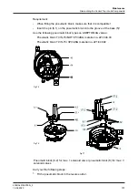
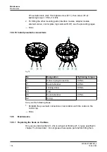
Place the logic element NOT, with adapter plate and seal, on the pneumatic
block (8) as shown in the illustration.
!
When inserting and tightening the screws, be careful to use existing threads.
Tightening torque 1.5 Nm (1.0 lbft).
Fig.71
®
Done
Hint!
Faulty assembly may cause malfunctions, as the spring force backup
is then not given.
Maintenance
Dismantling the Control Top into its Components
430BAL010697EN_2
98
15.04.2020
Содержание T.VIS M-15
Страница 6: ...430BAL010697EN_2 6 15 04 2020...
Страница 53: ...Fig 27 Assembly and installation Electrical connections 430BAL010697EN_2 15 04 2020 53...
Страница 55: ...Fig 28 Assembly and installation Electrical connections 430BAL010697EN_2 15 04 2020 55...
Страница 111: ...14 Spare parts list Switch bar T VIS M 15 Fig 82 Spare parts list Switch bar T VIS M 15 430BAL010697EN_2 15 04 2020 111...
Страница 119: ...Appendix 430BAL010697EN_2 15 04 2020 119...
Страница 120: ......


