


is at the bottom of the crankcase. To determine
the oil level, a sight glass is located on the
crankcase. To heat the oil, if necessary, all
compressors have a sleeve welded on to the
crankcase bottom, into which a heating element
(available as an accessory) can be inserted.
The oil which is separated in the suction chamber
from the refrigerant vapour can flow back to the
crankcase via a non-return valve. This valve is
fitted between suction chamber and crankcase in
the lower supporting ring of the cylinder liners
(except in the HP-cylinders in two-stage
compressors). The valve, normally open, closes
when the crankcase pressure exceeds the suction
pressure.
The crankcase interior is accessible via one or two
service covers provided on both sides of the
crankcase.
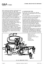
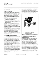
4.2 CYLINDERS AND MOVING PARTS (see fig. 4.1)
The cylinders are formed by interchangeable
cylinder liners pressed into the supporting rings in
the cylinder jackets. The collar on top of the
cylinder liners is provided with openings and acts
as a seat for the suction valve ring. In the cylinder
liners, light metal pistons are located, on which
three compression rings and one oil scraper ring
are fitted.
The connecting rods have a split-type big end, in
which white metal lined steel precision bearing
shells are positioned. To provide bearing for the
gudgeon pin, a bronze bush or, in the case of
HP-cylinders of two stage compressors, a needle
bearing is pressed into the small end.
The crankshaft is mounted in slide bearings
consisting of interchangeable white metal lined
steel bushes pressed into the bearing covers. The
crankshaft, furnished with cast-on counterweights,
is dynamically balanced. The tapered shaft end
with key for taking up flywheel or coupling, is
carried gastight through the bearing cover (see
par. 4.3, Rotary shaft seal).
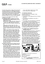
4.3 ROTARY SHAFT SEAL
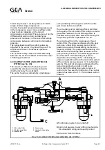
In order to pass the crankshaft (2) gastight
outwards, the compressor is provided with a
special rotary shaft seal, the construction of which
is shown in fig. 4.2.
The sealing between rotating and stationary parts
is effected on the sliding surface between a
carbon slip ring (7.1) rotating with the crankshaft
and a stationary counterslip ring (6) fitted in the
shaft seal housing (4). For this purpose the sliding
surface of both slip rings is ground to extreme
finish and lapped.
The carbon slip ring is carried by the slip ring
holder and forms an integral part of the rotary
seal assembly (7). This assembly consists of the
afore mentioned slip ring holder with carbon
insert, a metal bellows (7.2) and a drive collar
(7.3). The drive collar in turn is locked on the
FIG. 4.2 ROTARY SHAFT SEAL
1. Bearing cover
2. Drive pin
3. Rotary shaft seal assembly:
3a. Drive collar
3b. Metal bellows
3c. Slip ring holder with
carbon insert
4. O-ring
5. Grub screw
6. Shaft seal housing
7. Stationary counter-slip ring
8. Crankshaft
A
Oil supply from internal
lubricating circuit
B
Oil to oil pressure regulator
C
Oil leakage drain of rotary
shaft seal
Refrigeration Division
Grasso
4. GENERAL DESCRIPTION THE COMPRESSOR
Page 4.2
Refrigeration Compressors Series RC9
v002.97.10.en