Appendix
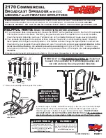
Hydraulic Diagram - DMI or Yetter Injectors
2018-9015-001
09-2016
11.15
Hydraulic Diagram - DMI or Yetter Injectors
1
5
5
4
2
1
6
3
7
Legend:
1
Tool bar hydraulic cylinder
5
Restrictor
2
Shredder hydraulic motor (optional)
6
Ball valve (included with recirculation kit)
3
Recirculation valve hydraulic cylinder
(optional)
7
Relief valve kit for pressurized tool bar
(optional)
4
Pressure relief valve
P
Pressure
T
Tank
C.D.
Case Drain