Changing the color of the timer
This device includes a Light Almond Faceplate. To
switch faceplates proceed as follows:
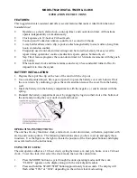
1. Gently remove the White Faceplate using a flat
head screwdriver. Starting at the top left corner
gently pry the faceplate loose. Work around the
faceplate until it pops off.
2. Find the Light Almond Faceplate in the package. Place the new faceplate into
position and carefully push until it snaps into position.
Multi-Switch Installations
When combining controls in a wall box, remove all inner side sections prior to wiring.
Use pliers to bend side section up and down until it breaks off. Repeat for each side
section to be removed.
If you are unsure or unclear about this installation or if the wires in your box do
not match the manual (not all switch boxes have neutral wires), contact a qualified
licensed electrician.
Installation Instruction (Single Pole)
1. Turn OFF the main power at the circuit breaker or fuse box.
2. Remove the existing switch.
3. Connect the wires of the timer to the wall box as shown in
Figure 1
and
Figure 2
using the wire nuts provided.
a) Connect the hot/live wire of line to the black wire from Timer.
b) Connect the hot/live wire of load to the blue wire from Timer.
c) Connect the ground wire to the green wire from Timer.
d) Connect the neutral wire to the white wire from the timer. Often the neutral
(white) wire can be found in the back of the wire box connected with a wire nut.
There may be several neutral wires bound together. Add the neutral to all neutral
wires bound together making sure wire nut is tight.
e) For single pole installation attach wire nut to red (traveler) wire from the back
of the timer. This wire is not needed in the single pole installation.
Note: Be sure that all wire nuts are secure.
4. Tuck the wires into the wall box leaving room for the timer. Using the screws
provided, mount the timer to the wall box being careful not to crush any wires.
5. Turn main power ON at the circuit breaker.
Typical 3-Way Wiring: In a typical 3-way application there are two 3-way switches.
The switch on the “HOT” side has the common terminal tied to 120VAC. The switch
on the “LOAD” side has the common tied to the lamp/load the switches turn OFF
and ON.
Common = Screw terminals found on the back single pole or 3-way toggle switch.
Existing 3-Way Installation Load Side
(The maximum distance between timer and 3-way switch is 100ft)
If timer is installed on the line side and all lamps burn out the timer will make a
ticking sound. (See Troubleshooting)
Switch on Line Side
1. Remove power from the circuit by turning off the circuit breaker
or removing fuse.
2. Remove the 3way switch from the hot/line side. Remove and label the common
wire and remove one of the other wires.
3. Using the supplied wire nuts connect the wire removed from the common, the
supplied jumper, and the other removed wire (1) together.
4. Connect the jumper back to the common connection of the switch.
5. If the two wires wire (1) and wire (5) on the switch are colored or marked so you
can tell them apart record their markings for use later.
6. Tuck the wires into box leaving room for switch.
7. Install switch into the box.
Timer on Load Side
1. Remove the load side 3-way switch and remove the 3 wires, labeling
the common wire.
2. Connect the removed common wire to the timer blue wire.
3. Connect wire (1) to the timer black (line) wire.
4. Connect wire (5) to the timer red (traveler) wire.
5. Connect the white wire (1) of the timer to the white wire in the switch box
(neutral). The neutral wires may be bundled in the back of the switch box with a
wire nut. There may be several neutral wires bound together. Add the neutral
to all neutral wires bound together making sure the wire nut is tight.
6. Connect the green wire (3) of the timer to ground in the switch box.
7. Tuck the wires into the switch box leaving room for the timer.
8. Use the supplied screws to install timer being careful not to crush
or pinch the wires.
9. Restore power at the circuit breaker or fuse box.
10. If the timer display does not turn on, you may need to swap wire (1) and wire (5).
This can be done at the timer or toggle switch, after removing power from the
circuit at the fuse box or circuit breaker.
11. Verify that the load turns ON and OFF when you manually turn the timer ON
and OFF. Perform this test with the remote switch in both positions. You should
hear the timer relay click ON/OFF. If you hear the relay click but the load does
not turn ON/OFF properly, check your wiring.
15312
12-17-2010
www.jascoproducts.com
Typical Wiring Schematic for Single Pole Installation
Black
Black
Load
White
White
White
Blue
Line
= Wiring Nut
Ground
Green
Timer
Figure 1
SunSmart
TM
Digital Timer
Installation
Instructions
Figure 2
RED
GREEN
BLUE
WHITE
BLACK
Load Side
Hot Side
Line
Neutral
H
H
H
H
C
C
Typical Wiring Schematic for 3-Way Installation
2
1
5
3
2
5
1
3
4
RED
GREEN
BLUE
GROUND
WHITE
BLACK
C
Typical Wiring Digram for 3-way installation
with timer on load side
Load
Line
1 = Line
2 = Neutral
3 = Ground
4 = Load
5 = Traveler
C = Common
Troubleshooting
Timer display is blank
• Circuit breaker or fuse has tripped.
• Neutral is not wired correctly.
Ticking can occur in 3-way application when timer is
installed on the line side and all lamps/bulbs on this
line are burnt out (or removed from the fixture)
• Turn other switch (load side) to off position to stop timer
from making ticking sound.
• Install a new bulb
• To permanently correct ticking issue re-install timer on
the load side. (See manual)
http://waterheatertimer.org/How-to-wire-GE-15312-timer.html