background image

 Critical Power 


Modifications reserved 

Page 4/46 

GE_UPS_OPM_SGS_ISG_10K_40K_0US_V070.docx 

Installation Guide

 SG Series 10-20-30-40 UL S


Preface 


Congratulations  on  your  choice  of  a 

SG  Series  10-20-30-40

  Uninterruptible  Power  Supply 

(UPS). It will help eliminate 

Load

 disturbances due to unexpected power problems. 


This 

Manual

  describes  the  function  of  the  UPS  module,  the  purpose  and  location  of  the 

switches,  the  meaning  of  the  system  events  related  to  the  front  panel  indication,  and 
provides procedures for starting and stopping the equipment. 


Please refer to the accompanying 

Installations Guide

, which describes how to prepare the 

installation site, and it provides weight, dimensions and procedures for moving, installing 
and connecting the UPS. 


While every care has been taken to ensure the completeness and accuracy of this manual, 

GE 

assumes no responsibility or liability for any losses or damages resulting from the use 

of the information contained in this document. 


NOTE! 

SG  Series  10-20-30-40

  is  a  product  that  needs  to  be  installed  by  a  licensed  and 

knowledgeable contractor. 


We recommend that this manual be kept next to the UPS for future references. 
If  any  problems  are  encountered  with  the  procedures  contained  in  this  manual,  please 
contact your 

Service Center

 before you proceed. 


This document shall not be copied or reproduced without the permission of 

GE


Some  of  the  information  contained  in  this  manual  may  be  changed  without  notice  to 
reflect technical improvements. 


Safety instructions 


Read  the  safety  instructions  contained  on  the  following  pages  carefully  before  the 
installation of the UPS, options and 

Battery System

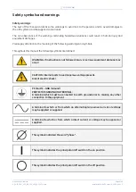
Pay attention to the rectangular boxes included in the text: 
They  contain  important  information  and  warning  concerning  electrical  connections  and 
personnel safety. 


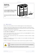
Parallel version secured with RPA


When included in the text, this symbol refers to operation needed 
only for parallel system. 

Содержание SG Series

Страница 1: ...de Uninterruptible Power Supply GE Consumer Industrial SA General Electric Company CH 6595 Riazzino Locarno Switzerland T 41 0 91 850 51 51 F 41 0 91 850 52 52 www gecriticalpower com g imagination at work SGT5000_030 040_UPS_GE_01a ...

Страница 2: ...C current rating 11 12 2008 5 0 ECN 1348 Soft 3 30 DSP 10 0 12 15 2009 6 0 ECN1548 Safety Rules 02 25 2011 7 0 ECN 2079 EPO for RPA Parallel System Customer Interface Board SNMP card GE Critical Power template 11 20 2014 COPYRIGHT 2014 by GE Consumer Industrial SA All rights reserved The information contained in this publication is intended solely for the purposes indicated The present publication...

Страница 3: ...e installation of the UPS Thank you for choosing GE START UP AND COMMISSIONING A GE GLOBAL SERVICES FIELD ENGINEER must perform start up and commissioning of the UPS Please Contact GE GLOBAL SERVICES at least two weeks prior to schedule start up and commissioning at 1 800 637 1738 or by E mail at pqservice ge com Distributed in the USA by Your service contact g GE Consumer Industrial SA General El...

Страница 4: ...or liability for any losses or damages resulting from the use of the information contained in this document NOTE SG Series 10 20 30 40 is a product that needs to be installed by a licensed and knowledgeable contractor We recommend that this manual be kept next to the UPS for future references If any problems are encountered with the procedures contained in this manual please contact your Service C...

Страница 5: ...3 8 2 Power connection with common input utility of SG Series 10 20 27 3 8 3 Power connection with common input utility of SG Series 30 40 28 3 8 4 Power connection dual input utility of SG Series 10 20 29 3 8 5 Power connection dual input utility of SG Series 30 40 31 3 8 6 Battery connection of SG Series 10 20 33 3 8 7 Battery connection of SG Series 30 40 34 3 8 8 Set up for SG Series 10 20 30 ...

Страница 6: ...e of the UPS for the following Damaged components squeezed wires and cables or not correctly inserted plugs After removing the sidewalls of the UPS make sure that all earth connections when reassembling are correctly reattached This UPS is intended for use in a controlled indoor environment free of conductive contaminants and protected against animals intrusion WARNING HIGH EARTH LEAKAGE CURRENT E...

Страница 7: ...fall into the battery cabinet 2 Tools must have insulated handles and must be insulated so that they will not short battery terminals Do not allow a tool to short between individual or separate battery terminals or to the cabinet or rack Do not lay tools or metal parts on top of the battery and do not lay them where they could fall onto the battery or into the cabinet 3 Install the battery as show...

Страница 8: ...his manual the following symbols are defined WARNING if instruction is not followed injury or serious equipment damage may occur CAUTION internal parts have dangerous voltage present Risk of electric shock PE Earth GND Ground PROTECTIVE GROUNDING TERMINAL A terminal which must be connected to earth ground prior to making any other connection to the equipment A terminal to which or from which an al...

Страница 9: ...1 3 SG Series 10 20 general view with optional 5th harmonic filter and removed protection panels 1 Opening for top cable entry 2 Opening for bottom cable entry 3 Terminals for Utility input and load output 4 Terminals for external Battery connection 5 Battery Shelf CR Connectivity Rack XA Terminals for 24Vdc Auxiliary Power Supply connection XB Terminals for EPO connection SGT5000_030 040_UPS_GE_0...

Страница 10: ...s 30 40 general view with optional 5th harmonic filter and removed protection panels 1 Opening for top cable entry 2 Opening for bottom cable entry 3 Terminals for Utility input and load output 4 Terminals for external Battery connection CR Connectivity Rack XA Terminals for 24Vdc Auxiliary Power Supply connection XB Terminals for EPO connection SGT5000_030 040_UPS_GE_02a SGT5000_030 040_UPS_GE_03...

Страница 11: ...e use suitable lifting straps and spreader bars Note of the center of gravity marked on the package Take all necessary precautions to avoid damage to the cabinet while hoisting the UPS NOTE Check for sufficient floor and elevator loading capacity 3 1 1 Dimensions and weight Fig 3 1 1 1 UPS cabinet dimensions Dimensions SG Series 10 20 30 40 W x D x H 26 78 x 31 50 x 70 90 inches 680 x 800 x 1 800 ...

Страница 12: ...with a temperature range not exceeding 13 F 25 C to 131 F 55 C In case the battery is included please refer to Section 3 3 2 Some important functions of the UPS such as the customized functions are defined by parameters stored in a RAM memory A small backup battery located on the Control Unit board supplies the RAM If the storage time of the UPS exceeds 1 year these functions should be verified by...

Страница 13: ...n 77 F 25 C will reduce battery life The SG Series 10 20 30 40 UPS can radiate radio frequency energy Although some RFI filtering is inherent to the UPS there is no guarantee that the UPS will not influence sensitive devices such as cameras and monitors that are positioned close by If interference is expected the UPS should be moved away from the sensitive equipment A single phase power outlet 120...

Страница 14: ... free from the floor and thus the cabinet supported on wheels After having positioned the UPS at its final location the cabinet has to be secured by rotating the bolts on each leg clockwise but the wheels must still touch the floor Fig 3 4 1 4 Bolts for the regulation of the cabinet The UPS cabinet is free standing and normally does not require to be bolted to the floor The UPS cabinet can be fixe...

Страница 15: ... within line of site to both the UPS and the battery The optimal room temperature for Battery location is 68 F 20 C to 77 F 25 C and shall never exceed the range 4 F 20 C to 104 F 40 C The life of valve regulated batteries will be reduced by 50 for each additional 18 F 10 C that the battery ambient temperature is above 77 F 25 C The battery system associated with larger UPS is usually either rack ...

Страница 16: ...PS room NOTE Do not put anything on the top of the cabinet Air filtration systems could be required when the UPS operates in a dirty environment Contact your Dealer or the nearest Service Center for appropriate solutions In order to prevent overheating of the UPS the available air intake flow rate must exceed the total air exhaust flow rate requirement of the UPS system The below table indicates t...

Страница 17: ...net packaged in Carton Box follow the instructions below 1 2 Make sure to have sufficient space around the UPS before you start unpacking Cut the three straps A fixing the carton box Remove package B and C Remove the protection D outside the cabinet and the accessories bag Remove the wooden support E which must be used to hoist the UPS Unscrew anchoring bolt F from plate on all four legs 3 4 Posit...

Страница 18: ...pport D underneath the UPS paying attention that the 2 guides D1 are positioned with the UPS in the center Lift the UPS cabinet Remove the wooden pallet G Loosen the 4 screws H and remove then the 4 anchoring plates I Put the UPS down on the floor Remove finally the wooden support D Included in the delivery you can find the following parts An accessories bag Control Bus cables only for RPA paralle...

Страница 19: ...ded The Bypass and Rectifier inputs are to be powered from different Utility supplies F1 and F2 inputs In this case when the Rectifier Input Fuses are opened the Bypass and the Manual Bypass are supplied by the other source In this case REMOVE the interconnection links BR1 BR2 and BR3 on the input terminals or bus bars See Fig 3 8 4 2 for SG Series 10 20 and Fig 3 8 5 2 for SG Series 30 40 Common ...

Страница 20: ...former the input protective devices should be sized to allow the transformer magnetization inrush current Caution when using four pole circuit breakers as protection A potential problem exists for situations with non linear loads The neutral current could be greater than the phase currents The three phase Utility power supply must be symmetrical with respect to ground due to the existence of volta...

Страница 21: ...ngs per phase These maximum and nominal ratings should be considered when choosing the appropriate AC over current protection device NEC National Electric Code Section 210 20 a rules must be applied DC current rating is the nominal battery discharge current which the UPS allows See Fig 3 7 1 1 and 3 7 1 2 UPS rating AC Input Rectifier AC Input Bypass AC Input DC Input F1 F2 F3 F4 Nom Max Nom Max S...

Страница 22: ...lus Ground AC INPUT BYPASS 3 Phase 4 wire plus Ground AC OUTPUT 3 Phase 4 wire plus Ground DC INPUT 2 wire positive and negative plus Ground Maximum cable diameter that terminals can accept Refer to torque specifications table for torque requirements UPS rating Rectifier Input Bypass Input DC Input AC Output GND SG Series 10 3 AWG 3 AWG 3 AWG 3 AWG 3 AWG SG Series 20 3 AWG 3 AWG 3 AWG 3 AWG 3 AWG ...

Страница 23: ...5 10 30 35 40 25 30 35 8 40 50 55 30 40 45 6 55 65 75 40 50 60 4 70 85 95 55 65 75 3 85 100 110 65 75 85 2 95 115 130 75 90 100 1 110 130 150 85 100 115 1 0 125 150 170 100 120 135 2 0 145 175 195 115 135 150 3 0 165 200 225 130 155 175 4 0 195 230 260 150 180 205 250 215 255 290 170 205 230 300 240 285 320 190 230 255 350 260 310 350 210 250 280 400 280 335 380 225 270 305 500 320 380 430 260 310...

Страница 24: ...e top of the cabinet remove the cover plate fitted on the roof and provide for a suitable isolated protection cover In case of cable entry from the bottom remove cover plate and perform the same procedure The input output cables must be connected in clockwise phase rotation for both Bypass and Rectifier Input Terminals if separate taking care to avoid risk of short circuit between different poles ...

Страница 25: ...the input output connections of SG Series 10 20 To access input output and Battery connections proceed as follows Remove protection panel A Remove protection panel B Remove UPS side panel C Only for Dual Input Utility Remove with appropriate tool the metallic window D from the metal screen C A C B Bottom entry cables Top entry cables SGUL_010 020_UPS connection_01US D E Please remove the plate E F...

Страница 26: ...the input output connections of SG Series 30 40 To access input output and Battery connections proceed as follows Remove protection panel A Remove protection panel B Remove UPS side panel C Only for Dual Input Utility Remove with appropriate tool the metallic window D from the metal screen C D Bottom entry cables Top entry cables A B C E before drilling any wholes Please remove the plate E F SGUL_...

Страница 27: ...hase C N Load Neutral PE Load Ground The interconnection links BR1 BR2 and BR3 MUST REMAIN CONNECTED Cable terminations are to the Rectifier Input Terminals and Output Terminals as shown above Connect wire to the Terminals using appropriate tools and appropriate torque Torque specification for Input Output and DC power connections on Terminals see Section 3 8 1 NOTE This UPS is only designed to op...

Страница 28: ...N Load Neutral PE Load Ground The interconnection links BR1 BR2 and BR3 MUST REMAIN CONNECTED Cable terminations are to the Rectifier Input Terminals and Output Terminals as shown above Connect wire to the Terminals using appropriate tools and appropriate torque Torque specification for Input Output and DC power connections on Terminals see Section 3 8 1 NOTE This UPS is only designed to operate i...

Страница 29: ...connection links BR1 BR2 and BR3 MUST BE REMOVED see Fig 3 8 4 2 Output Load L1 Load Phase A L2 Load Phase B L3 Load Phase C N Load Neutral PE Load Ground Cable terminations are to the Rectifier Bypass Input Terminals and Load Output Terminals as shown above Connect wire to the Terminals using appropriate tools and appropriate torque Torque specification for Input Output and DC power connections o...

Страница 30: ...allation Guide SG Series 10 20 30 40 UL S Notices for installation Fig 3 8 4 2 Interconnection links BR1 BR2 and BR3 of SG Series 10 20 For separate Bypass and Rectifier Input configuration the interconnection links BR1 BR2 and BR3 MUST BE REMOVED SGT5000_010 020_UPS BR1 2 3_01 X2 X1 BR2 BR1 BR3 ...

Страница 31: ...ion links BR1 BR2 and BR3 MUST BE REMOVED see Fig 3 8 5 2 Output Load L1 Load Phase A L2 Load Phase B L3 Load Phase C N Load Neutral PE Load Ground Cable terminations are to the Rectifier Bypass Input Terminals and Load Output Terminals as shown above Connect wire to the Terminals using appropriate tools and appropriate torque Torque specification for Input Output and DC power connections on Termi...

Страница 32: ...n Guide SG Series 10 20 30 40 UL S Notices for installation Fig 3 8 5 2 Interconnection links BR1 BR2 and BR3 of SG Series 30 40 For separate Bypass and Rectifier Input configuration the interconnection links BR1 BR2 and BR3 MUST BE REMOVED X1 SGT5000_030 040_UPS BR1 2 3_01 OFF ON OFF ON X2 BR1 BR2 BR3 ...

Страница 33: ...oncerning electromagnetic compliance the connection between the UPS and external battery must be done by using a shielded cable or suitable shielded metal conduit This UPS is only designed to operate in a wye configured electrical system with a solidly grounded neutral If the UPS is equipped with an input transformer for the secondary of the transformer must be wye configured with neutral solidly ...

Страница 34: ...shown above Connect wire to the Terminals using appropriate tools and appropriate torque Torque specification for Input Output and DC power connections on Terminals See section 3 8 1 NOTE To meet standards concerning electromagnetic compliance the connection between the UPS and external battery must be done by using a shielded cable or suitable shielded metal conduit This UPS is only designed to o...

Страница 35: ...e transferred to Manual Bypass serious damage to the load could result The handle of the switch Q2 Manual Bypass should be removed to avoid attempts to transfer to Manual Bypass when the UPS is being used as a frequency converter As an added measure of safety the interconnection links BR1 BR2 and BR3 should also be removed See Fig 3 8 4 2 SG Series 10 20 or Fig 3 8 5 2 SG Series 30 40 Fig 3 8 8 1 ...

Страница 36: ...l m n o p q r Tolerance 10 The AC input power of the Bypass must be the same for all units of the parallel system no phase shift allowed between units NOTE It is strongly recommended that no transformers automatic circuit breakers or fuses should be inserted between the unit s output and the Load common bus bars However it is recommended that a disconnection or isolation switch is installed in ord...

Страница 37: ...d between units in case one of the control cables should fail or be accidentally damaged or disconnected The standard length of the control bus cable between two parallel unit is 40 ft 12 m Maximal overall length of bus connection between the first and the last unit should not be longer than 276 ft 84 m Verify that control wiring is run in individual separate steel conduit NOTE Under no circumstan...

Страница 38: ...ion on intermediate units Intermediate units On the parallel bus PCB P34 Bus Interface of the intermediate units of the parallel system the Jumpers JP1 JP2 JP3 and JP4 MUST BE REMOVED NOTE In a parallel system composed of 2 or more units only the first and last units having 1 input JA and JB free have the Jumper JP1 JP2 JP3 and JP4 inserted on parallel bus PCB P34 Bus Interface see Fig 3 9 2 2 SGT...

Страница 39: ...tween parallel units must be made on the front of the electronic module fitted behind the front doors Fig 3 9 3 2 Front view electronic module on intermediate unit Control bus cables connection Plug the cables JA 1 2 3 4 5 6 7 and JB 1 2 3 4 5 6 7 onto the RJ connectors JA and JB located on parallel bus PCB P34 Bus Interface going to P13 RPA Board J52 A and J62 B Fix both cables JA 1 2 3 4 5 6 7 a...

Страница 40: ... removed from the parallel system the bus cables JA and JB must be removed from the cabinet without disconnecting them from the metal plate where the sockets JA and JB are located For reliability reasons the cables JA 1 2 3 4 5 6 7 and JB 1 2 3 4 5 6 7 connecting the units should be run in separated protected conduits as indicated in Fig 3 9 3 3 separated from the power cables It is important that...

Страница 41: ...m default Parameter RL 6 Input contacts see Section 4 1 3 X1 10 21 or J2 10 23 Programmable default RL1 X1 11 22 or J2 11 24 Programmable Generator ON NO def RL2 NO Normally Open C Common NC Normally Closed The connectors J4 and J5 can be used for additional 3 ph SNMP WEB plug in adapter or an additional Customer Interface installation only when the UPS is switched Off XA terminals for 24Vdc Auxil...

Страница 42: ...ignals are available either on connector J2 sub D female 25 pin or terminal blocks X1 The meaning of the alarms on the free contacts in standard configuration default is the following X1 1 2 3 or J2 1 2 3 NO C NC Utility Failure X1 4 5 6 or J2 4 5 6 NO C NC Load on Inverter X1 7 8 9 or J2 7 8 9 NO C NC Stop Operations X1 12 13 14 or J2 14 15 16 NO C NC Load on Utility X1 15 16 17 or J2 17 18 19 NO...

Страница 43: ...sequently the Load transfer to generator Reduction or elimination or delay of Battery recharging during the generator operation In a parallel system a separate NO Normally Open contact must be connected to each individual unit 4 1 5 AUX external Maintenance Bypass If the UPS system is equipped with an external Maintenance Bypass Switch it is possible to connect a NO Normally Open voltage free aux ...

Страница 44: ...een already connected on XB or J2 When opened this contact causes the immediate opening of the Contactors K3 K4 K6 K7 and K8 as well as the shut down of Rectifier Inverter and Static Switch NOTE This procedure could imply a load shut down NOTE In case of parallel Customer Interface the EPO contact must be connected to one P4 Customer Interface only but the bridge on X2 and jumper JP3 on the P4 Cus...

Страница 45: ...ctivated the system must be restored as follows Realize the push button EPO Emergency Power Off contact on XB 1 4 is closed again Press the key O Inverter OFF Shut down on the Control Panel see User Manual to Section 5 2 In case of a Parallel System press the key O Inverter OFF on the Control Panel of each unit connected on the Parallel Bus and having its output switch Q1 closed ...

Страница 46: ...70 docx Installation Guide SG Series 10 20 30 40 UL S 5 NOTES 5 1 NOTES FORM It is recommended to note in this section Notes with date and short description all the operations performed on the UPS as maintenance components replacement abnormal situations etc Date Description Done by ...

Отзывы: