


Critical Power
Modifications reserved
Page 33/46
GE_UPS_OPM_SGS_ISG_10K_40K_0US_V070.docx
Installation Guide
SG Series 10-20-30-40 UL S
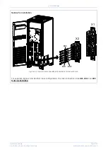
3.8.6
Battery connection of
SG Series 10 & 20
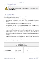
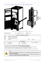
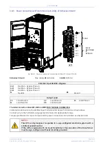
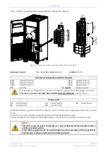
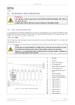
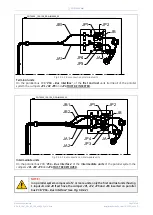
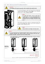
Fig. 3.8.6-1 Power connections of internal / external battery for SG Series 10 & 20
Max. rating
Battery terminals
:
3 AWG
(25mm
2
)
Battery
+
Positive pole of the Battery
–
Negative pole of the Battery
Do not insert the
Battery Fuses
before the commissioning.
Battery cable terminations are to the
Positive
and
Negative Terminals
as shown above.
Connect wire to the
Terminals
using appropriate tools and appropriate torque.
Torque specification for
Input / Output
and
DC
power connections on
Terminals
:
See section 3.8.1.
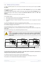
NOTE !
To meet standards concerning electromagnetic compliance, the connection
between the UPS and external battery must be done by using a shielded cable or
suitable shielded (metal) conduit!
This UPS is only designed to operate in a wye-configured electrical system with a
solidly grounded neutral.
If the UPS is equipped with an input transformer for, the secondary of the
transformer must be wye-configured with neutral solidly grounded.
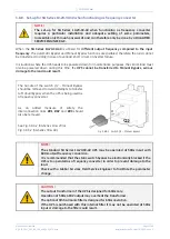
NOTE !
When an additional battery cabinet is connected, no batteries must be installed
inside the UPS cabinet.
SGT
50
00_
0
10-0
20_
U
P
S
co
nne
ct
io
n
ba
tt
er
y_01
_
+
BC
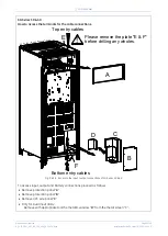
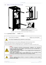
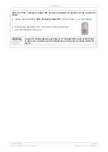
When the unit is equipped with internal battery, for safety reasons it is
The battery plug "BC" must be connected to the battery connector fitted on
External battery connection
Internal battery connection
delivered with the battery fuses already inserted, but with the
battery plug "BC" disconnected.
battery enclosure just before the commissioning.


