


Modifications reserved
Page 45/49
OPM_SGS_ISG_M75_M75_2US_V010.doc
Installation Guide
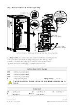
SG Series 750 UL S2
&
SG Series 750 T12 UL S2
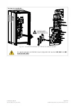
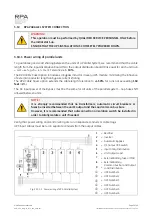
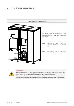
4.1 CUSTOMER INTERFACE
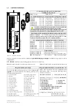
J3 - Serial port RS 232 (sub D - female 9 pin)
Suitable for GE protocol
Pin 2
: TX (out)
Pin 3
: RX (in)
Pin 5
: GND
J2 - (subD-female 25 pin) – Output signals on voltage free contacts
J2
/
1, 2, 3
NO, C, NC Utility Failure
(default Parameter RL=1)
J2/4, 5, 6
NO, C, NC Load on Inverter (default Parameter RL=3)
J2/7, 8, 9
NO, C, NC Stop Operation
(default Parameter RL=5)
J2/14, 15, 16
NO, C, NC Load on Utility
(default Parameter RL=2)
J2/17, 18, 19
NO, C, NC General Alarm
(default Parameter RL=4)
J2/20, 21, 22
NO, C, NC Acoustic Alarm
(default Parameter RL=6)
Signals on terminals
X1
and on connector
J2
are in parallel and
therefore not separated galvanically from each other.
The programmable signals on
X1
and
J2
will be disabled with
Q1
open, with
the exception of the signals for
“16 - Manual Bypass ON”
and
“26 - EPO”
.
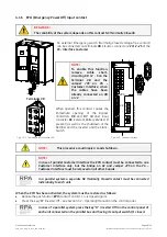
Terminals for
EPO
connection (for XB terminals see
Section 4.1.6
)
XB/1, 4
or
J2/12, 25
NC
EPO
(Emergency Power Off) - See
Section 4.7.1
Note: to enable this function, remove cable short-circuiting
XB / 2 – 3
(see
Section 4.1.6
) and the Jumper
JP3
on P4 – Customer Interface
.
X1 – Output signals on voltage free contacts - terminals
X1/1, 2, 3
NO, C, NC Utility Failure
(default Parameter RL=1)
X1/4, 5, 6
NO, C, NC Load on Inverter (default Parameter RL=3)
X1/7, 8, 9
NO, C, NC Stop Operation
(default Parameter RL=5)
X1/12, 13, 14
NO, C, NC Load on Utility
(default Parameter RL=2)
X1/15, 16, 17
NO, C, NC General Alarm
(default Parameter RL=4)
X1/18, 19, 20
NO, C, NC Acoustic Alarm
(default Parameter RL=6)
Input contacts
X1/10, 21
or
J2/10, 23
Programmable (default = RL1)
X1/11, 22
or
J2/11, 24
Programmable / Generator ON (NO) (def. = RL2)
1
12
13
2
14
3
15
4
16
5
17
6
18
7
19
8
20
9
21
10
22
11
1
14
9
1
X1
J2
J3
S
G
S
_7
50
_C
us
to
m
er
in
terface_
01
J5
2
1
JP3
XA
1
1
2
2
3
3
4
4
XB
41
32
41
32
3
2
1
3
2
1
2
11
2
X1
X4
X3
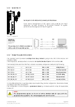
Fig. 4.1-1 Customer interface
NO
= Normally Open
C
= Common
NC
= Normally Closed
J5
: This connector can be used for additional
3-ph SNMP/WEB plug-in adapter
(installation only when the UPS is
switched Off).
P27 - IM0108
: Interface to External Bypass (see
Section 3.9.5
and
3.9.6
).
XA
: terminals for 24Vdc connection (see
Section 4.1.5
).
XB
: terminals for
EPO
connection (see
Section 4.1.6
).
Programmable user relays
Programmable functions on contacts (X1 - J2)
On terminals
X1
or
J2
connector, six of the following
27
signals
can be selected from the display, entering with
the appropriate password.
0- No Information
1- Buzzer
2- General Alarm
3- Load on Utility
4- Stop Operation
5- Load on Inverter
6- Utility Failure
7- DC Over Voltage
8- Low Battery
9- Overload
10- Over Temperature
11- Inverter-Utility not syncron.
12- Bypass Locked
13- Bypass Utility Failure
14- Rectifier Utility Failure
15- Battery Discharge
16- Manual Bypass ON
17- Rectifier ON
18- Inverter ON
19- Boost Charge
20- Battery Earth Fault
21- Battery Fault
22- Relay Input 1
23- Relay Input 2
24- Relay Output ON
25- Relay Output OFF
26-
EPO
(Emergency Power Off)
27- eBoost/IEMi mode
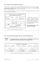
Some UPS functions can be activated with
parameters when an external Normally Open
contact is closed on:
X1-10, 21 / J2-10, 23
or
X1-11, 22 / J2- 11, 24
Selectable functions by changing
parameters
(password required) are:
0 - No function
1 - Inverter ON
2 - Inverter OFF
3 - Print All
4 - Status Relay
5 - Generator ON
6 - External Bypass ON
7 - External Battery Fuses, or External K3
See Alarm 4104 - “Battery Fuses”
8 – eBoost/IEMi control
Voltage free contacts: Max. DC / AC: 24V / 1.25A
IEC 60950 (SELV circuit)
Min. Signal Level: 5Vdc/5mA


