


Modifications reserved
Page 39/49
OPM_SGS_ISG_M75_M75_2US_V010.doc
Installation Guide
SG Series 750 UL S2
&
SG Series 750 T12 UL S2
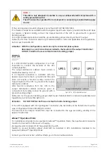
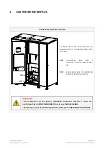
3.10 RPA PARALLEL SYSTEM CONNECTION
WARNING !
This operation must be performed by QUALIFIED SERVICE PERSONNEL ONLY before
the initial start-up.
ENSURE THAT THE UPS INSTALLATION IS COMPLETELY POWERED DOWN.
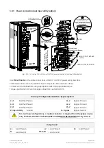
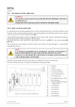
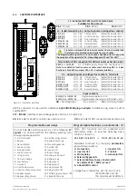
3.10.1 Power wiring of parallel units
To guarantee good
Load
sharing between the units of a
Parallel System
, we recommend that the cable
length from the input distribution board (5) to the output distribution board (9) is equal for each unit (a+b
= c+d = e+f = g+h = i+l = m+n). Tolerance:
+/- 10%
.
The
RPA Cable Saver
option introduces a bypass inductor in every UPS module, minimizing the influence
of external conductor length on bypass current sharing.
The
RPA Cable Saver
option extends the cable length tolerance to
+/-50%
for runs not exceeding
160
feet
(49m).
The AC input power of the
Bypass
must be the same for all units of the parallel system - no phase shift
allowed between units.
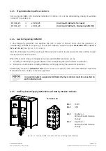
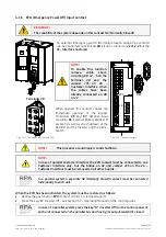
NOTE !
It is strongly recommended that no transformers, automatic circuit breakers or
fuses be inserted between the unit’s output and the
Load
common bus bars.
However, it is recommended that a disconnection or isolation switch be installed in
order to totally isolate a unit if needed.
Verify that power wiring and control wiring are run in separate conduits or cable trays.
UPS input cables must be run in separate conduits from the output cables.
1
= Rectifier
2
= Inverter
3
= Automatic Bypass
4
= Q1 Output UPS switch
5
= Input Utility Distribution
6
= Unit Output Load
7
= External Battery fuse or MCB
8
= External Battery
9
=
Common bus bar and Output
Load Distribution
c
= UPS Number 1
2
= UPS Number 2
3
= UPS Number 3
4
= UPS Number 4
5
= UPS Number 5
Fig. 3.10.1-1 Power wiring of RPA Parallel System
6
= UPS Number 6