background image

Modifications reserved 

Page 19/49 

OPM_SGS_ISG_M75_M75_2US_V010.doc 

Installation Guide 

SG Series 750 UL S2 

&

 SG Series 750 T12 UL S2


3.6 

UNPACKING 

 
The UPS and 

Battery Cabinets

 may be shipped packaged in wooden crates. 

Move the cabinets as close as possible to the final location before removing from the pallet. 
Remove the cabinet from the wooden crates with care, because of the heavy weight of the equipment. 


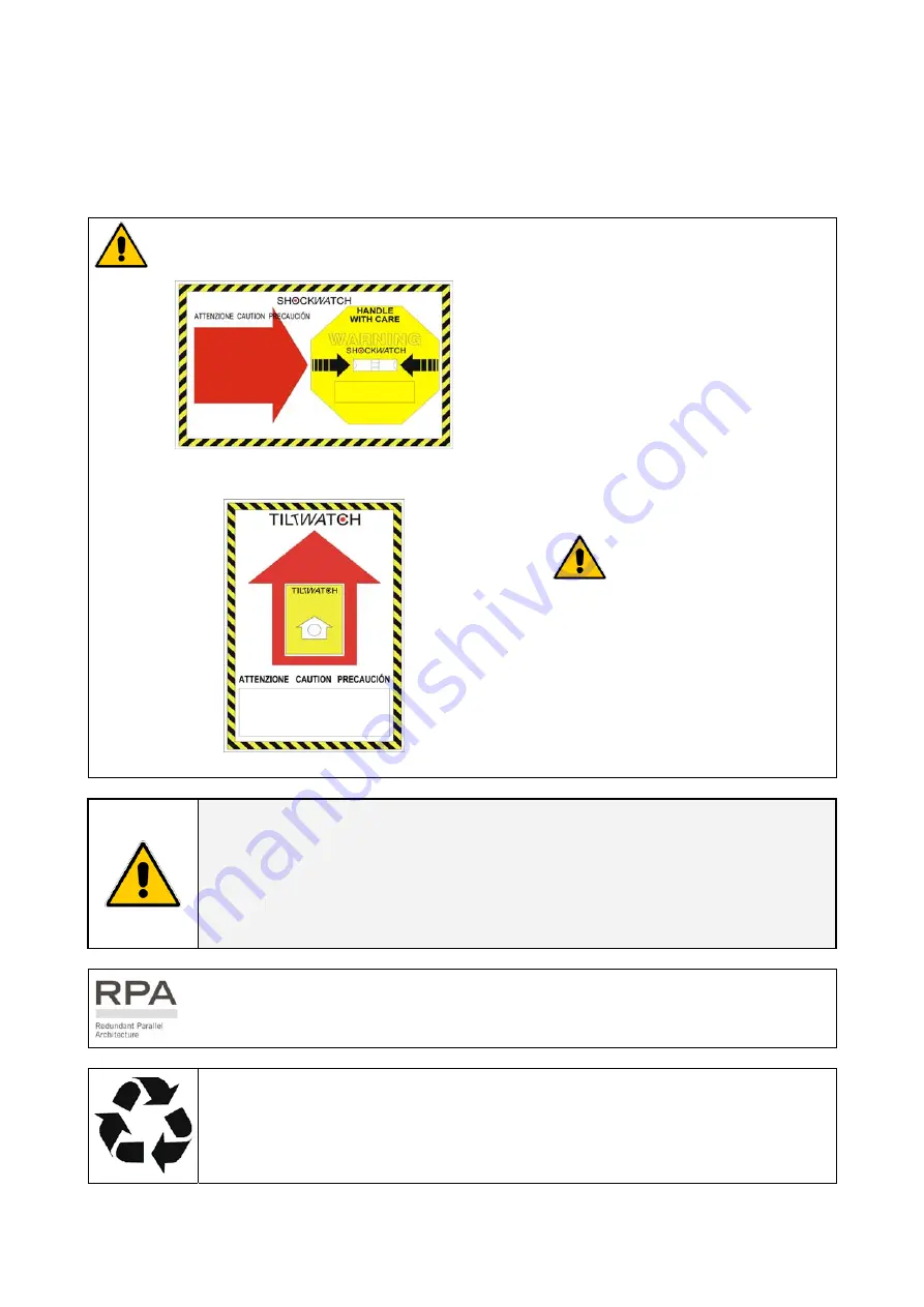
White color


=


without any anomaly 

Red color


=


anomaly evidence 


Fig. 3.6-1   ShockWatch device


Fig. 3.6-2   TiltWatch device


The package of the 

SG Series 750 

SG Series 750 T12 

is equipped with 

ShockWatch

 (indicator for shock), 

and 

TiltWatch

 (indicator for 

overthrow) on the outside. 
 
These devices indicate an eventual 
shock or overthrow during transport. 


Whenever these devices show a 
possible anomaly, the UPS shall not 
be commissioned before consulting 

“Service Center”

.


NOTE ! 

Take care not to damage the UPS when moving by forklift. 
A damaged UPS must never be installed or connected to 

Utility

 or 

Battery!


In case of any damage sustained during the transport, immediately inform the 
shipping agent! 
A detailed report of the damage is necessary for any indemnity claim.


For parallel systems, the delivery also includes the bus control cables for inter-
connecting the UPS modules.


Packing material recycling 

GE

, in compliance with environment protection, use only environmentally friendly 

material. 
UPS packing materials must be recycled in compliance with all applicable 
regulations.


Содержание SG 750 T12 UL S2 Series

Страница 1: ...de Uninterruptible Power supply SG Series 750 UL S2 SG Series 750 T12 UL S2 750 kVA 480Vac UL S2 GE Consumer Industrial SA General Electric Company CH 6595 Riazzino Locarno Switzerland T 41 0 91 850 51 51 F 41 0 91 850 52 52 www gepowerquality com imagination at work ...

Страница 2: ...COPYRIGHT 2010 by GE Consumer Industrial SA All rights reserved The information contained in this publication is intended solely for the purposes indicated The present publication and any other documentation supplied with the UPS system is not to be reproduced either in part or in its entirety without the prior written consent of GE The illustrations and plans describing the equipment are intended...

Страница 3: ...s all the necessary information and describes all you need to know about the installation of the UPS Thank you for choosing GE START UP AND COMMISSIONING A GE GLOBAL SERVICES FIELD ENGINEER must perform start up and commissioning of the UPS Please Contact GE GLOBAL SERVICES at least two weeks prior to schedule start up and commissioning at 1 800 637 1738 or by E mail at pqservice ge com Distribute...

Страница 4: ... losses or damages resulting from the use of the information contained in this document NOTE SG Series 750 SG Series 750 T12 is a product that needs to be installed by a licensed and knowledgeable contractor We recommend that this manual be kept next to the UPS for future references If any problems are encountered with the procedures contained in this manual please contact your Service Center befo...

Страница 5: ...24 3 8 2 Input output over current protection and wire sizing 25 3 8 3 Battery over current protection and wire sizing 26 3 9 WIRING CONNECTION 28 3 9 1 Power connections 28 3 9 2 Power connection with common input utility 31 3 9 3 Power connection dual input utility option 33 3 9 4 Battery and External Battery Breaker connection 36 3 9 5 Interface to External Bypass for single unit 37 3 9 6 Conne...

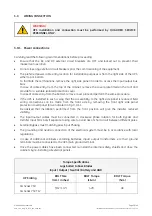
Страница 6: ... connections when reassembling are correctly reattached This UPS is intended for use in a controlled indoor environment free of conductive contaminants and protected against animals intrusion WARNING HIGH EARTH LEAKAGE CURRENT Earth connection is essential before connecting to AC input Switching OFF the unit does not isolate the UPS from the utility Do not install the UPS in an excessively humid e...

Страница 7: ...ll into the battery cabinet 2 Tools must have insulated handles and must be insulated so that they will not short battery terminals Do not allow a tool to short between individual or separate battery terminals or to the cabinet or rack Do not lay tools or metal parts on top of the battery and do not lay them where they could fall onto the battery or into the cabinet 3 Install the battery as shown ...

Страница 8: ... manual the following symbols are defined WARNING if instruction is not followed injury or serious equipment damage may occur CAUTION internal parts have dangerous voltage present Risk of electric shock PE Earth GND Ground PROTECTIVE GROUNDING TERMINAL A terminal which must be connected to earth ground prior to making any other connection to the equipment A terminal to which or from which an alter...

Страница 9: ...s 750 UL S2 SG Series 750 T12 UL S2 2 LAYOUT 2 1 LAYOUT SG Series 750 SG Series 750 T12 SGS_750_UPS_GE_01 Fig 2 1 1 SG Series 750 SG Series 750 T12 general view 2 2 INVERTER CABINET LAYOUT SG Series 750 SG Series 750 T12 SGS_750_UPS_Inverter cabinet_GE_01 Fig 2 2 1 Inverter cabinet general view ...

Страница 10: ...t_GE_03b Q1 4 1 3 XB XA SS CR1 CR2 2 14 15 3 4 16 17 5 6 19 20 8 9 18 7 22 11 1 21 10 12 1 2 13 3 4 2 1 2 3 1 4 2 Fig 2 3 3 General rectifier cabinet view without protection panels 1 Opening for top cable entry 2 Opening for bottom cable entry 3 Bus bars for Utility input and Load output 4 Bus bars for external Battery connection CR1 Connectivity Rack with a Customer Interface CR2 Connectivity Rac...

Страница 11: ...raps and spreader bars Note of the center of gravity for rectifier and inverter cabinet marked on the package Forklift The UPS may be lifted with a forklift in upright position Take note of the CENTER OF GRAVITY marked on the package Forklift Centre of Gravity Centre of Gravity Fig 3 1 1 Position of the forklift when moving the unpacked rectifier cabinet WARNING Check for sufficient floor and elev...

Страница 12: ...he CENTER OF GRAVITY marked on the package Take all necessary precautions to avoid damage to the cabinet while hoisting the UPS Crane Fig 3 1 3 Position of the carrying belts when moving the unpacked rectifier cabinet and inverter cabinet WARNING PLEASE DO NOT LIFT UNPACKED UPS CABINETS USING A CRANE WARNING When loading unloading and when moving the UPS it is forbidden When loading unloading and ...

Страница 13: ...12 Inverter cabinet 79 5x35 4x76 8 inches 2020x900x1950 mm SG Series 750 SG Series 750 T12 Rectifier cabinet 67x35 4x76 8 inches 1700x900x1950 mm Weights SG Series 750 SG Series 750 T12 and options Weight lbs Kg Floor Load lbs sq ft Kg m2 UPS rating with Rectifier Configuration Rectifier Inverter Rectifier Inverter SG Series 750 6 pulse with 5th filter 3468 1573 6332 2872 211 1028 324 1580 SG Seri...

Страница 14: ...y from chemical substances and with a temperature range not exceeding 13 F 25 C to 131 F 55 C In case the battery is included please refer to Section 3 3 2 Some important functions of the UPS such as the customized functions are defined by parameters stored in a RAM memory A small backup battery located on the Control Unit board supplies the RAM If the storage time of the UPS exceeds 1 year these ...

Страница 15: ...gher than 77 F 25 C will reduce battery life The SG Series UPS can radiate radio frequency energy Although some RFI filtering is inherent to the UPS there is no guarantee that the UPS will not influence sensitive devices such as cameras and monitors that are positioned close by If interference is expected the UPS should be moved away from the sensitive equipment SG Series 750 SG Series 750 T12 pos...

Страница 16: ...etal filings from cutting conduit entry holes Fig 3 4 1 2 SG Series 750 SG Series 750 T12 opening on top of the cabinet for input output cables Utility input Output Load Battery SGS_750_UPS view bottom_01US 28 74 108mm 4 25 863mm 33 98 730mm 1663mm 65 47 349mm 13 74 28mm 1 1 Rectifier cabinet NOTE Remove this panel or provide means to capture metal filings from cutting conduit entry holes Fig 3 4 ...

Страница 17: ...remotely from the UPS a wall mounted DC disconnect device must be installed within line of site to both the UPS and the Battery The optimal room temperature for Battery storage is 68 F 20 C to 77 F 25 C and shall never exceed the range 4 F 20 C to 104 F 40 C The life of valve regulated batteries will be reduced by 50 for each additional 18 F 10 C that the Battery ambient temperature is above 77 F ...

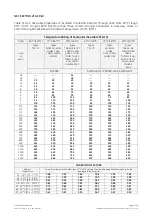
Страница 18: ...er or the nearest Service Center for appropriate solutions In order to prevent overheating of the UPS the available air intake flow rate must exceed the total air exhaust flow rate requirement of the UPS system The below tables indicate the heat dissipation at full Load at PF 0 9 lag and charged Battery up to 3 280 ft 1 000 m altitude for cooling air 77 F 25 C to 86 F 30 C Losses Cooling air flow ...

Страница 19: ...ch indicator for overthrow on the outside These devices indicate an eventual shock or overthrow during transport Whenever these devices show a possible anomaly the UPS shall not be commissioned before consulting a Service Center NOTE Take care not to damage the UPS when moving by forklift A damaged UPS must never be installed or connected to Utility or Battery In case of any damage sustained durin...

Страница 20: ...on the right side cabinet with control panel Pay attention that no loose cables are trapped when pushing the cabinets together Inverter cabinet Rectifier cabinet 190mm 7 5 680mm 26 8 g Rectifier cabinet frame Spacer aluminium M8 flat washer Bolt M8x60 Inverter cabinet frame M8 Nut with washer Detail showing the interconnection of the inverter and rectifier cabinets To bolt only on the front side 2...

Страница 21: ...g 3 7 1 2 1 Interconnection Bypass Line 1 1 Bus bar of size 40 x 10mm Type 1 2 Interconnection Bypass Line 2 1 Bus bar of size 40 x 10mm Type 1 3 Interconnection Bypass Line 3 1 Bus bar of size 40 x 10mm Type 1 4 Interconnection for Inverter output Line 1 1 Bus bar of size 40 x 10mm Type 1 5 Interconnection for Inverter output Line 2 1 Bus bar of size 40 x 10mm Type 1 6 Interconnection for Inverte...

Страница 22: ... DC Earthing BOLT Size mm M10 BOLT Torque Lb in 266 BOLT Torque N m 30 Type 1 Pre Fixed Nut M10 Flat Washer M10 Spring Washer Bolt M10x35 Bus Bar Pre Fixed Nut Bolt M10x35 M10 Spring Washer M10 Flat Washer Bus Bar Type 2 Type 3 Flexi Bar Spacer Copper M10 Flat Washer Bolt M10x70 M10 Flat Washer Bus Bar Flexi Bar M10 Nut Type 4 Pre Fixed Nut Bolt M10X25 M10 Spring Washer Cabinet Base M10 Flat Washe...

Страница 23: ...et Rectifier cabinet see Pos 5 Female connector HAN 18 Refer Fig 3 7 3 2 3 Male connector HAN 32 Inverter cabinet Rectifier cabinet see Pos 5 Female connector HAN 32 Refer Fig 3 7 3 2 Flat cable with connector 10 pin Inverter cabinet P3 IM0007 Control Board Rectifier cabinet see Pos 2 J33A IM0174 Adapter Board 4 Flat cable with connector 26 pin Inverter cabinet P3 IM0007 Control Board Rectifier ca...

Страница 24: ...nput option sources if desired Dual Input Configuration Rectifier Bypass recommended The Bypass and Rectifier inputs are to be powered from different Utility supplies F1 and F2 inputs In this case when the Rectifier Input Fuses are opened the Bypass is supplied by the other source In this case REMOVE the interconnection links BR1 BR2 and BR3 on the input terminals or bus bars See Fig 3 9 3 3 Commo...

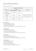
Страница 25: ...mer the input protective devices should be sized to allow the transformer magnetization inrush current Caution when using four pole circuit breakers as protection A potential problem exists for situations with non linear loads The neutral current could be greater than the phase currents The three phase Utility power supply must be symmetrical with respect to ground due to the existence of voltage ...

Страница 26: ... with 5th filter 920 1103 902 902 1103 1512 1793 SG Series 750 6 pulse with 5th 11th filter 900 1080 902 902 1080 1512 1793 SG Series 750 T12 12 pulse without filter 1082 1306 902 1082 1306 1512 1793 SG Series 750 T12 12 pulse with 11th filter 1032 1245 902 1032 1245 1512 1793 DC over current sized to support maximum DC current Size of Branch Circuit Over current Protection All Models CAUTION To r...

Страница 27: ... 55 65 75 40 50 60 4 70 85 95 55 65 75 3 85 100 110 65 75 85 2 95 115 130 75 90 100 1 110 130 150 85 100 115 1 0 125 150 170 100 120 135 2 0 145 175 195 115 135 150 3 0 165 200 225 130 155 175 4 0 195 230 260 150 180 205 250 215 255 290 170 205 230 300 240 285 320 190 230 255 350 260 310 350 210 250 280 400 280 335 380 225 270 305 500 320 380 430 260 310 350 600 355 420 475 285 340 385 700 385 460...

Страница 28: ...If the UPS is installed in such a way that the accessibility to the right side panel is reduced field wiring connections can be made from the front side by removing the front right side panel protection cover panel A as indicated in Fig 3 9 1 1 Be advised that installation performed from the front position will give the installer reduced visibility The input output cables must be connected in cloc...

Страница 29: ...How to access the input output and DC bus bars for the cable connections SGS_750_S2_UPS connection_GE_01_US B A Bottom entry cables Top entry cables Rectifier cabinet NOTE Remove this panel or provide means to capture metal filings from cutting conduit entry holes NOTE Remove this panel or provide means to capture metal filin from cutting conduit entry h 4 3 13 2 1 12 10 21 1 11 22 7 18 9 8 20 19 ...

Страница 30: ...r each unit 15 are used for AC Rectifier input 3 lines 5 are used for Neutral bypass input Terminal lugs are secured to metal plate or to bus bars by means of two bolts Connection type B 28 Lugs in total are used for each unit 12 are used for AC Bypass input 3 Lines 16 are used for AC Output 3 Lines and Neutral Terminal lugs are secured to metal plate or to bus bars by means of two bolts Connectio...

Страница 31: ...ns to the wit 2 bolts M4x10 BR1 BR2 and BR3 Fig 3 9 2 1 SG Series 750 SG Series 750 T12 power connections Common Input Utility Use M12x35 bolts for the cable connections on INPUT OUTPUT Power Wiring Bus Bars Cable terminations are to the Rectifier Input Output Bus Bars as shown above Connect wire to the Bus Bars using appropriate tools and appropriate torque Torque specification for two hole lugs ...

Страница 32: ...The output distribution cabinet must contain a Neutral Bus see Fig 3 9 2 2 If no Neutral Connection is available with the Bypass Input 3 wire input ground and the Load does not require a Neutral solidly connect the Output Neutral of the UPS to ground in the Output Distribution Cabinet Wire Neutral Conductors from the UPS to the output distribution cabinet common point of connection and solidly con...

Страница 33: ...L2 2 L3 3 option Fig 3 9 3 1 SG Series 750 SG Series 750 T12 power connections Dual Input Utility option Use M12x35 bolts for the cable connections on INPUT OUTPUT power wiring Bus Bars Cable terminations are to the Rectifier Input Output Bus Bars as shown above Connect wire to the Bus Bars using appropriate tools and appropriate torque Torque specification for two hole lugs on Bus Bars see Sectio...

Страница 34: ...The output distribution cabinet must contain a Neutral Bus see Fig 3 9 3 2 If no Neutral Connection is available with the Bypass Input 3 wire input ground and the Load does not require a Neutral solidly connect the Output Neutral of the UPS to ground in the Output Distribution Cabinet Wire Neutral Conductors from the UPS to the output distribution cabinet common point of connection and solidly con...

Страница 35: ...50 T12 UL S2 Notices for installation SGS_750_UPS BR1 2 3_GE_01 BR1 BR2 and BR3 MUST BE REMOVED In case of dual input utility BR1 BR1 BR1 BR1 BR2 BR3 Fig 3 9 3 3 SG Series 750 SG Series 750 T12AC bus bars BR1 BR2 and BR3 For separate Bypass and Rectifier input configuration AC bus bars BR1 BR2 and BR3 MUST BE REMOVED ...

Страница 36: ...egative pole of the Battery Do not insert the Battery Fuses before the commissioning NOTE To meet standards concerning electromagnetic compliance the connection between the UPS and external Battery must be done by using a shielded cable or suitable shielded steel conduit External Battery Breaker Release Fig 3 9 4 2 External battery breaker connection For connection or disconnection of the Battery ...

Страница 37: ...verter Output Contactor K7 opens and the Load transfer to Inverter will be inhibited Fig 3 9 5 1 Interface to External Bypass for single unit SG Series 750 SG Series 750 T12 has to be interfaced to the External Bypass Auxiliary Contacts NO for safety reasons This will prevent contactor K7 from closing when the external bypass breaker is on The connections shown in the diagram are mandatory 3 9 6 C...

Страница 38: ...ystems intended to be operated in eBoost Operation Mode the installation shall be protected with suitable surge protection devices SPDs on the AC bus feeding the UPSs Please contact your Service Center for more information When using the eBoost IEMi control function on the programmable user relays of the customer interface X1 J2 terminals in a Parallel System a separate NO Normally Open contact mu...

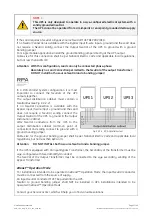
Страница 39: ...extends the cable length tolerance to 50 for runs not exceeding 160 feet 49m The AC input power of the Bypass must be the same for all units of the parallel system no phase shift allowed between units NOTE It is strongly recommended that no transformers automatic circuit breakers or fuses be inserted between the unit s output and the Load common bus bars However it is recommended that a disconnect...

Страница 40: ... units in case one of the control cables should fail or be accidentally damaged or disconnected The standard length of the control bus cable between two parallel unit is 40 ft 12 m Maximal overall length of bus connection between the first and the last unit should not be longer than 276 ft 84 m Verify that control wiring is run in individual separate steel conduit NOTE Under no circumstance should...

Страница 41: ...stem the Jumpers JP1 JP2 JP3 and JP4 MUST BE INSERTED SGS_750_RPA IM0048_03 JB1 JA1 JA2 JB2 JP2 JB JA JP2 JP1 JP4 IM 0048 JP3 JP1 JP4 JP3 Fig 3 10 2 3 Bus connection on intermediate units Intermediate units On the parallel bus PCB P34 Bus Interface IM0048 of the intermediate units of the parallel system the Jumpers JP1 JP2 JP3 and JP4 MUST BE REMOVED NOTE In a parallel system composed of 2 or more...

Страница 42: ...electronic module on intermediate unit Access to the control bus connection The control bus connection between parallel units must be made on the electronic module P34 Bus Interface IM0048 situated at the inside of the UPS door SGS_750_RPA control bus cable_02US Next parallel unit A B JA JA2 JB2 JB1 JA1 JB Fig 3 10 3 2 Front view electronic module on intermediate unit Control bus cables connection...

Страница 43: ...when cabling and routing the bus cables JA and JB inside the UPS cabinet In case one unit should be removed from the parallel system the bus cables JA and JB must be removed from the cabinet without disconnecting them from the metal plate where the sockets JA and JB are located For reliability reasons the cables JA 1 2 3 4 5 and JB 1 2 3 4 5 connecting the units should be run in separated protecte...

Страница 44: ...4 3 4 14 15 3 4 16 17 5 6 12 1 2 13 1 SG Series 750 SG Series 750 T12 are delivered with 2 Connectivity Rack CR1 and CR2 CR1 Connectivity Rack with a Customer Interface see Section 4 1 CR2 Connectivity Rack for additional Customer Interface option WARNING The installation of the option Additional Customer Interface must be performed by a SERVICE ENGINEER from of your Service Center The operation m...

Страница 45: ...1 22 or J2 11 24 Programmable Generator ON NO def RL2 1 12 13 2 14 3 15 4 16 5 17 6 18 7 19 8 20 9 21 10 22 11 1 14 9 1 X1 J2 J3 SGS_750_Customer interface_01 J5 2 1 JP3 XA 1 1 2 2 3 3 4 4 XB 4 1 3 2 4 1 3 2 3 2 1 3 2 1 2 1 1 2 X1 X4 X3 Fig 4 1 1 Customer interface NO Normally Open C Common NC Normally Closed J5 This connector can be used for additional 3 ph SNMP WEB plug in adapter installation o...

Страница 46: ...ce board provides 6 voltage free relay contacts giving some UPS critical alarms and operation mode These signals are available either on connector J2 sub D female 25 pin or terminal blocks X1 The meaning of the alarms on the free contacts in standard configuration default is the following X1 1 2 3 or J2 1 2 3 NO C NC Utility Failure X1 4 5 6 or J2 4 5 6 NO C NC Load on Inverter X1 7 8 9 or J2 7 8 ...

Страница 47: ...nearest Service Center for it s activation When this contact closes it changes certain programmable functions such as Enabling or disabling of synchronization and consequently the Load transfer to generator Reduction or elimination or delay of Battery recharging during the generator operation Additionally when the Generator ON input contact is closed the UPS will inhibit eBoost Operation Mode and ...

Страница 48: ...K6 and K7 Rectifier input contactor K4 External Battery Breaker if present as well as the shutdown of the Rectifier and the Inverter and the Static Switch 1 12 13 2 14 3 15 4 16 5 17 6 18 7 19 8 20 9 21 10 22 11 1 14 9 1 J2 SGS_750_Customer interface_J2 JP3_01 2 1 JP3 1 1 2 2 3 3 4 4 XB 4 1 3 2 4 1 3 2 3 2 1 3 2 1 2 1 1 2 Fig 4 1 6 2 Customer interface NOTE This procedure could imply a Load shutdo...

Страница 49: ... Guide SG Series 750 UL S2 SG Series 750 T12 UL S2 5 NOTES 5 1 NOTES FORM It is recommended to note in this section Notes with date and short description all the operations performed on the UPS as Maintenance components replacement abnormal situations etc Date Description Done by ...

Отзывы: