


SecoGear 24kV-27kV Air Insulation Switchgear
15
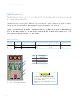
Cable Connections
The cable compartment contains current transformers, voltage transformers (fixed or withdrawable), and earthing switch, depending
on the individual operating requirements.
The cable compartment is constructed for installation of three current transformers. When all the three current transformers are not
required, dummies can be installed in their place to maintain the same installation and connection procedures.
The fixed or withdrawable voltage transformers are connected with busbar on the primary side and fitted with HRC fuses. The earthing
switch can be operated manually, with position indication by mechanical indicator on the driveshaft and auxiliary switch. Three
lightning arrestors (optional) can be mounted in the space available.
Cable connection:
Rated voltage
Panel width
Max. number of parallel cables Max. cross section of cables Range of cable clamp
Range of reducer ring
(kV)
(mm )
per Phase
(mm
2
)
(mm)
(mm)
27
800
6
630
35-54
27-62
1000
6
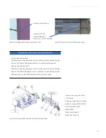
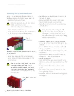
Figure 3/13: Cable compartment layout
NO.
Parts Description
1
Cable clamp
2
Main earthing bar
3
Cable connection bar
4
Earthing Switch
1
2
3
4
This cover has been interlocked with the earthing
switch and can be opened only when the earthing
switch is in closed position
Earthing switch can be opened only when rear cover
is closed


