background image

GEI-88767 

the  incoming  side  of  a  power  transformer,  the  primary  bus1or  to  cables  by 

the  use  of  potheads.  When  applied  with  power  fuses,  the  combination 

serves  as  a  successful  switching  and  fault  protection  device. 

Operation  of  the  switch  is  accomplished  by  manual  rotation  of  a  handle 

through  an  arc  of  180°.  The  SE-lOOS  switch  has  a  positive  closing  and 

opening  operation  supplied  from  the  stored  energy  of  springs.  The  SE-

lOOM  handle  must  be  operated  manually  with  a  full  positive  motion  to 

assure  proper  closing  and  opening  with  the  direct  drive  mechanism.  The 

operating  handle  is  often  interlocked  with  other  devices  such  as  secon-

dary  circuit  breakers  in  order  to  assure  sequential  operation. 

The  SE-lOOE  switch  is  normally  operated  by  energizing  an  integral  elec­

tric  motor  that  charges  the  springs  for  positive  closing  and  opening 

similar  to  the  handle  of  the  SE-1003.  The  switch  can  be  quickly  con­

verted  from  electrical  to  manual  operation  with  a  handle  for  normal 

maintenance  or  emergency  use. 

The  interrupting  ability  of  the  switch  is  accomplished  by  the  use  of 

an  arc  chute  type  interrupter 

(5) 

Fig.  4  and  an  auxiliary  blade  (3). 

When  the  switch  is  opened  the  auxiliary  blade  contacts  (2 

3)  are  the 

last  to  part  and  will  initiate  an  arc  in  the  chute.  The  hot  arc  re­

leases  gases  from  the  plastic  chute  in  such  volume  that  the  arc  is 

blown  away  from  the  rapidly  moving  auxiliary  blade  and  cooled  by  con­

tact  with  the  large  area  of  the  chute  sides.  After  the  arc  has  been 

extinguished,  the  blade  will  continue  to  open  producing  a  sufficient 

air  gap  to  isolate  the  terminals. 

AND 

STORAGE 

and 

Immediately  upon  receipt  of  the  switch,  an  examination  should  be  made 

for  loss  or  damage  sustained  in  transit.  If  injury  or  rough  handling 

is  evident,  a  damage  claim  should  be  filed  immediately  with  the  trans­

portation  company  and  the  nearest  General  Electric  Apparatus  Sales 

Office  should  be  notified. 

Although  damage  due  to  handling  is  minimized  because  of  the  metal  en­

closure,  it  is  expected  that  due  care  will  be  exercised  in  the  unpack-

ing  and  installation  of  the  switch  unit  so  that  no  damage  will  occur  from 

careless  or  rough  handling,  or  from  exposure  to  moisture  or  dirt.  Care 

should  be  exercised  to  prevent  tools  from  striking  any  part  of  the  hous-

ing  or  switch  iteslf. 

Loose  parts  associated  with  the  switch  are  alwars  included  in  the  same 

crate.  Check  all  parts  against  the  packing  list  to  be  sure  that  no 

parts  have  been  overlooked. 

It  is  recommended  that  the  switch  be  placed  into  service  immediately  in 

its  permanent  location. 

If  this  is  not  possible,  the  following  precau-

tions  should  be  taken  to  iQsure  proper  storage  conditions: 

Содержание SE-100E

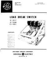
Страница 1: ...duction 1 Ratings 1 Receiving HancUing and Storage 2 Ins Callation 3 scription of Operation SE lOOE SE 1008 4 SE lOOM ll Adjustments SE 100E SE 1008 5 SE 1QQ I 12 Final Inspection 13 Renewal Parts 15 Lubrication Chart 16 Schematic Wiring Diagram SE lOOE 16 SWITCHGEAR PRODUCTS DEPARTMENT GENERAL fj ELECTRIC PHILADELPHIA PA ...

Страница 2: ...reater than those given on the nameplate The chart below gives the ratings for the basic switches SE 100 Switch Ratings N ominal Max Design BIL Continuous Load Break Close Latch Momentar 1 1 oltage Voltage KV Current Current Current Current KV KV Atnps Amps Amps KA filtll 4 8 5 5 60 600 600 40 000 40 gg 4 8 5 5 60 1200 1200 61 000 61 r lr 1 13 2 15 5 95 600 600 40 000 40 rk gJtll 13 2 15 5 95 1200...

Страница 3: ... in the chute The hot arc re leases gases from the plastic chute in such volume that the arc is blown away from the rapidly moving auxiliary blade and cooled by con tact with the large area of the chute sides After the arc has been extinguished the blade will continue to open producing a sufficient air gap to isolate the terminals RECEIVING HANDLING AND STORAGE Receiving and Handling Immediately u...

Страница 4: ...d be used to prevent twisting Connection The connections on the 600 ampere switch may be made from above or below the insulator support The 1200 ampere switch must have the upper connections above the upper insulator support and the lower connection below the hinge support insulator Connection of bus bars to this terminal can easily be made u ing the provided terminal bolts After connections to th...

Страница 5: ...ng 4 Fig 1 located on the right side and compress it fully Continued rotation of the handle will push the spring over the toggle position and it will start to discharge A driving lug 5 Fig 2 will engage the drive crank 3 which is directly connected to the main crank shaft 11 Fig 2 just as the primary spring leaves the toggle position When the main crank shaft has rotated a few de rees the fully ch...

Страница 6: ...n crank shaft has rotated a few degrees past the primary spring toggle position the spring will dis charge opening the switch and charging the booster spring 5 Fig 1 for the next closing operation The primary blade 11 Fig 7 travel will cause the primary contacts 5 to part first and the arcing contacts 6 a few degrees later The spring loaded auxiliary blade 3 Fig 4 will remain latched to the contac...

Страница 7: ...tch for adjusting purposes Upper Closed Mechanism Stop The upper buffer stops 3 Fig 5 located on either side of the mecha nism at the ends of the main crank shaft must be adjusted to position the operating rod cranks when the switch is closed Operate the switch to the fully closed position The operating rod must go over toggle approximately k at the crank connection when the switch is closed A sim...

Страница 8: ...le and note the engagement of the primary contacts 4 arc ing contacts 6 8 and guide block 10 The blades should center around the guide block without bearing heavily on either side They should also be centered in the primary and arcing contact fingers If the blades press hard against the sides of the guide block loosen the 2 bolts 11 Fig 8 holding the block Again check the contact alignment If the ...

Страница 9: ...ottom to the top of the support to decrease the gap To increase the gap move some of the top shims to the bottom support When the release gap is properly set check again the dimension from the back edge of the chute to the primary contact finger support and the alignment of the auxiliary blade in the chute opening Auxiliary Blade Release The auxiliary blade release hook 14 Fig 7 should be adjusted...

Страница 10: ...d Move the nut in increments of one sixth of a turn to assure line up of cotter pin hole and slot in the nut Control Power Check SE lOOE After the switch has been opened and closed several times with the maintenance closing handle and all adjustments have been checked as described the operating voltage should be checked at the motor ter minal board For electrical operation of the mechanism the con...

Страница 11: ...at the time of periodic maintenance and requires no dis assembly The second method outlines a lubrication procedure similar to that performed on the device at the factory but should be used only in case of a general overhaul or disassembly for other reasons General Electric Lubricants D50Hl5 and D50H47 are available in 1 4 col lapsible tubes It is so packaged to insure cleanliness and to prevent o...

Страница 12: ... SE lOOM The SE lOOM switch has a direct mechanical drive and the closing and opening energy is supplied by the operator When operating the switch the handle should be rotated with a posi tive motion throughout its entire stroke Closing Operation Closing the switch is accomplished by inserting the operating handle l Fig 3 into the handle socket provided in the operating hub 7 Fig 1 in the enclosur...

Страница 13: ...to Page 7 Primary Contact Alignment Close the primary blades 12 Fig 8 nance handle and note the engagement guide block 10 The blades should out bearing heavily on either side the primary contact fingers slowly by the use of the mainte of the primary contacts 4 and center around the guide block with They should also be centered in If the blades press hard against the sides of the guide block loosen...

Страница 14: ...ightness 2 See that all bearing surfaces of the mechanism have been lubri cated 3 Operate the device slowly several times by hand and note that there is no binding or excessive friction 4 See that any place where the surface of the paint has been dam aged during installation is repainted immediately 5 Replace all barriers covers and any other parts that may have been removed during installation Hi...

Страница 15: ...hich have been removed from service and stored over an extended period of time under unfavorable atmospheric conditions NOTE Before applying a hi potential test make certain that the switch has been disconnected from both the source and load If the SE lOOE secondary wiring is to be given a hi potential test at 1500 volts remove both of the motor leads from the terminal board Failure to disconnect ...

Страница 16: ...pring All 6 161A5829 P 1 161A5829 P 1 Not Req Arcing Contact Blade 600 3 105C9366 P 4 105C9366 P 4 Not Req Arcing Contact Blade 1200 3 105C9366 G 1 105C9366 G 1 Not Req Arc Chute Assembly 4 8KV 600 3 105C9350 G 1 10509350 G 1 10509350 G 2 Arc Chute Assembly 4 8KV 1200 3 105C9350 G 1 105C9350 G 1 Not Avail Arc Chute Assembly 13 2KV All 3 10509350 G 2 lOS0935Q G 2 10509350 G 2 Auxiliary Blade 4 8KV ...

Страница 17: ...Light application of SAE 20 30 oil Apply D50Hl5 grease Light application of SAE 20 30 oil at rear oil hole only Clean bearings then apply D50Hl5 grease Wipe clean and apply D50Hl5 grease Light application of SAE 20 30 oil at rear oil hole only Fig 11 LUBRICATION CHART _L LOsE L CONTROL LS I SWITCH 7 FUSED SOURCE t l I p i CONTROL LR SWITCH 2 5 CLOSE RELAY LS 6 S LR 6 OPEN RELAY 16 3T AS 3 SWITCH S...

Страница 18: ...ng Stop Bolt lA Spring Stop Bolt 2 Spring Stop 3 Driving Crank 4 Hole for Spring Blocking Pin 5 Driving Lug 6 Buffer Rubber 7 Buffer Stop 8 Operating Rod 9 Operating Rod Crank 10 Operating Hub 11 Main Crank Shaft 12 Maintenance Handle GEI 88767 Fig 1 SE lOOS Switch Partially Open 4 8 a l 2 t 4 L 3 6 7 5 9 11 10 1 _ 12 Fig 2 Spring Drive Mechanism 17 ...

Страница 19: ... 6 7 8 9 10 11 1 Sperating Handle 2 Maintenance Handle 3 Spring Blocking Pin 1 Blade Stop Block 2 Arc Chute Contacts 3 Auxiliary Blade 4 Spacer 5 Arc Chute Side 6 Primary Contact Blade 7 Auxiliary Blade Spring 8 Camming Screw 9 Lock Nut 10 Auxiliary Blade Release Hook 11 Operating Rod ...

Страница 20: ...er Buffer Stop 1 Auxiliary Blade Spring 2 Auxiliary Blade Release Hook 3 Spring Stop 4 Carruning Screw 5 Lock Nut 6 Adjusting Nut 7 Release Hook Spring 8 Operating Rod 9 Operating Rod Crank 10 Main Crank Shaft GEI 88767 11 2 4 3 Fig 5 Buffer Assembly Fig 6 Switch Blade Adjustments 19 ...

Страница 21: ...hute Mounting Bolts Primary Contact Blade Auxiliary Contact Blade Rivot Pin for Auxiliary Blade Auxiliary Blade Release Hook Operating Rod Clevis Pin Hinge Pin 1 2 3 4 5 6 7 8 9 10 11 12 Fig 8 Contact Arrangement Arc Chute Mounting Bolts Upper Terminal Shims Primary Contacts Contact Bolts Arcing Contact Fingers Contact Bolt Movable Arcing Contact Tube Spacer Guide Block Buffer Block Bolts Primary ...

Страница 22: ...hute Stationary Primary Contact Primary Blade Stop Primary Blade 1 Auxiliary Switch 2 Motor 3 Start Stop Relay GEI 88767 Fig 9 Unit Pole Fully Open 3 5 1 4 Close Relay 5 Open Relay Fig 10 Electrical Operator 21 ...

Страница 23: ... Dr t Roanoke 24015 2018 Colonial Ave WASHINGTON t t Seattle 98188 112 Andover Park East Tukwila Spokane 99202 E 1805 Trent Ave WEST VIRGINIA t Charleston 25328 306 MacCorkll Ave SE WISCONSIN Appleton 54911 t Milwaukee 53202 3003 West College Dr 615 E M1chigan St WHEN YOU NEED SERVICE These GE Service Shops will repatr re condition and rebuild your electric apparatus The facilities are available d...

Отзывы: