– 2 –
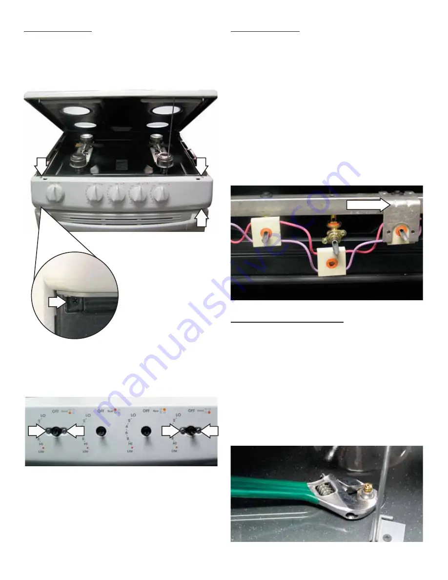
MANIFOLD PANEL
There are 8 screws that hold the manifold panel in
place.
4 Screws (Behind the Gas Control Knobs)
4 Screws (Top and Bottom of the Manifold Panel)
SWITCH REMOVAL
1. Prop open the cooktop.
2. Remove the gas control knobs, then remove the
manifold panel.
3. To remove the switch, rotate the switch 15-20
degrees counterclockwise and pull the switch off
the manifold.
Note:
For switches located behind the bracket, the
valve must fi rst be removed from the manifold.
All 4 switches come as an assembly.
•
•
TOP BURNER VALVE REMOVAL
1. Remove the switch from the valve. (See
Switch
Removal.
)
2. For the desired valve, remove the
1
/
4
-in. hex-
head screw on the manifold.
3. Lift burners off the orifi ces, then locate the
orifi ce that corresponds to the desired valve.
4. Remove the
3
/
4
-in. hex nut holding the orifi ce
and tube assembly as shown.
Bracket
Содержание RGA724PK
Страница 5: ...5 Wiring Diagram...
Страница 6: ...6 Schematic...


