


– 19 –
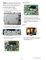
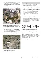
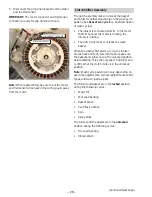
3. The pressure sensor is held in place by 3 tabs.
With a fl at-blade screwdriver, press the tabs
back and lift the water level switch up and out.
4. Disconnect the clear hose from the pressure
sensor.
Disconnect
Clear Pressure Hose
Tab
Tab
Tab
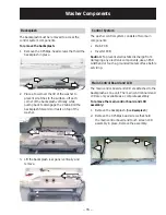
Water Valve Assembly
The water valve consists of a valve body and fi ve
solenoid coils. It is only available as a complete
assembly. Each solenoid controls a specifi c water
function.
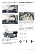
Each coil on the water valve assembly has an
•
approximate resistance value of 30
Ω
.
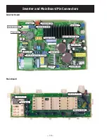
Each coil receives power from the inverter. They
•
are connected to the 6-pin blue connector on
the inverter board. (See
I
nverter and Main Board
Pin Connectors.
)
When energized, there should be approximately
•
13 VDC at the appropriate coil.
To remove the water valve assembly:
Remove the backsplash. (See
1.
Backsplash
.)
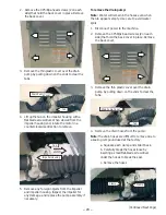
Water Distribution Pipe
Water Valve Assembly
Hot Water
Cold Water
Additive
Softener
Bleach
(Continued Next Page)
Pressure Sensor
To remove the pressure sensor:
Remove the backsplash. (See
1.
Backsplash
.)
Disconnect the wiring harness from the pressure
2.
sensor.
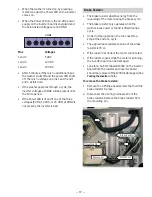
Black
Dk. Blue
Lt. Blue White Lt. Blue White
Pink
1
6
5
7
2
8
3
9
4
10
Yellow
Dk. Blue
Orange
Black
Brown
Y
ellow
Dk. Blue
Gray
D k . B l u e
1
6
5
2
3
4
I n v e r t e r
HV
CV
Additive
Bleach
Softener
Содержание Profile WPGT9150
Страница 37: ... 37 ...
Страница 38: ... 38 Schematic P No 3858EL3002E ...


