


GE Healthcare
Direction 5743854-1EN, Revision 1 Optima XR642/XR648 Pre-Installation
Chapter 2 - Equipment
Page 77
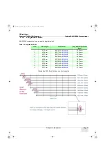
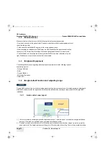
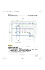
range for dongle location if selecting position1, and the adjusting range is 1 meter both in left and right direction.
3.) Position2 is in the corner of control room. Height requirement is same as position2, 30cm lower to the ceiling. No
adjusting range for this location.
4.) Dongle angle shall be 45 degrees toward the wall.
5.) Site preparation shall reserve the conduit for position1/2 and adjusting range to make sure the dongle cables could
be routed inside the conduit.
6.) There shall be no metal obstacle within the 20 cm range of dongle installation position
7.) There shall be no obstacle between dongle and digital cassette area
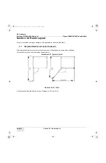
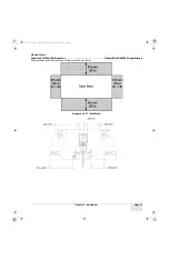
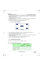
3.4.2
Outside control room layout
1.) There is only one default dongle installation – position1, it’s the center position of the examination room
2.) Dongle installation position’s height shall be 30cm lower than the ceiling
3.) Dongle angle shall be 45 degrees toward the wall.
4.) Site preparation shall reserve the conduit for position1/2 and adjusting range to make sure the dongle cables could
be routed inside the conduit.
5.) There shall be no metal obstacle within the 20 cm range of dongle installation position
6.) There shall be no obstacle between dongle and digital cassette area
3.5
Configurations and option
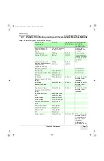
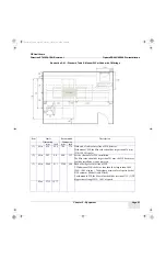
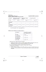
In Table Below, Room configurations supported for the System are selected.
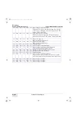
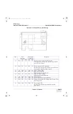
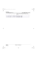
Table 2-7 Optima XR642/XR648 System Configuration
System
Wall Stand
Type
Bridge Length, Wall Stand
Position
2M Bridge
3M Bridge
Front Back Head Foot
Front Back Head Foot
Global URP WS Only
Standard
√
√
√
√
Global URP WS Only
Extended
√
√
√
√
Manual WS Only
Manual
√
√
√
√
Manual WS &
Standard Table
Manual
√
√
Pre-Install.book Page 77 Tuesday, January 30, 2018 2:36 PM


