GEK-113188A
MIGII Digital Protection for Electrical Machines
6-1
6 I/0 CONFIGURATION
6.1 INPUT CONFIGURATION
6
6 I/0 CONFIGURATION 6.1INPUT CONFIGURATION
6.1.1 DESCRIPTION OF INPUTS
MIGII incorporates 2 digital inputs, which can be configured using the ENERVISTA MII SETUP software (
Setpoint >
Relay Configuration
). The default input configuration is as follows:
Input 1:
Emergency Reset
Input 2:
External Trip
All elements not defined as PULSE are LEVEL inputs.
In LEVEL inputs, while the voltage level is enough to activate the input, the input performs the function stated in its
configuration.
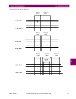
PULSE inputs are different. In the configuration menu for each input there are several states already defined as Pulse
inputs. When the input recognizes their activation, it performs the function stated in its configuration, independently from
the time it remains activated. For the input to perform again the required function, it is required that the input voltage level
is reset and reactivated.
Figure 6–1: INPUT RESPONSE FOR LEVEL AND PULSE OPTIONS
The minimum operation time for a valid PULSE input is over 0.015 seconds.
Input elements are divided into four groups, two of them with eight elements per group, another group with two elements,
and the last one with four elements besides besides the
No definition
one. Up to eight elements can be configured to be
activated by the same input, providing that they are all in the same group. Elements belonging to different groups need to
be assigned to different inputs.
In order to configure an input with more than one element from the same group, we must first activate the
OR
button, click
on the
I/O CONFIGURATION
option and select the desired group, then select the desired elements. For inverting an
element, select the
NOT
button. Finally, click the
OK
button.
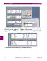
INPUT CONFIGURATION WITH MORE THAN ONE FUNCTION (OR). EXAMPLE
As shown on the figure below, input 1 is assigned to an OR. Clicking on that OR checkbox, a second screen named "OR
ASSIGNMENT" is displayed, where the user can select the group that contains the desired elements (in this example,
"INHIBITIONS BY DIGITAL INPUT 1"). This group includes 8 elements, from which we can select the ones we want to
operate in the input, and invert them by clicking on the NOT checkbox. In the example below, all functions have been
LEVEL
Input
configuration
response
PULSE
Input
configuration
response
Содержание Multilin MIGII
Страница 2: ......
Страница 114: ...5 24 MIGII Digital Protection for Electrical Machines GEK 113188A 5 4 TIME SYNCHRONIZATION 5 SETTINGS 5 ...
Страница 136: ...8 8 MIGII Digital Protection for Electrical Machines GEK 113188A 8 4 OPERATIONS 8 KEYPAD AND DISPLAY 8 ...
Страница 137: ...GEK 113188A MIGII Digital Protection for Electrical Machines 8 9 8 KEYPAD AND DISPLAY 8 4 OPERATIONS 8 ...
Страница 138: ...8 10 MIGII Digital Protection for Electrical Machines GEK 113188A 8 4 OPERATIONS 8 KEYPAD AND DISPLAY 8 ...
Страница 139: ...GEK 113188A MIGII Digital Protection for Electrical Machines 8 11 8 KEYPAD AND DISPLAY 8 4 OPERATIONS 8 ...
Страница 140: ...8 12 MIGII Digital Protection for Electrical Machines GEK 113188A 8 4 OPERATIONS 8 KEYPAD AND DISPLAY 8 ...
Страница 141: ...GEK 113188A MIGII Digital Protection for Electrical Machines 8 13 8 KEYPAD AND DISPLAY 8 4 OPERATIONS 8 ...
Страница 142: ...8 14 MIGII Digital Protection for Electrical Machines GEK 113188A 8 4 OPERATIONS 8 KEYPAD AND DISPLAY 8 ...
Страница 143: ...GEK 113188A MIGII Digital Protection for Electrical Machines 8 15 8 KEYPAD AND DISPLAY 8 4 OPERATIONS 8 ...
Страница 144: ...8 16 MIGII Digital Protection for Electrical Machines GEK 113188A 8 4 OPERATIONS 8 KEYPAD AND DISPLAY 8 ...
Страница 200: ...A 10 MIGII Digital Protection for Electrical Machines GEK 113188A A 6 MIGII THERMAL CURVES APPENDIXA A ...
Страница 208: ...B 8 MIGII Digital Protection for Electrical Machines GEK 113188A B 2 ANSI CURVES APPENDIXB B Figure B 4 ANSI INVERSE ...
Страница 230: ...C 20 MIGII Digital Protection for Electrical Machines GEK 113188A C 8 MODBUS MAP STATUS APPENDIXC C ...


