2 | GE Oil & Gas
© 2015 General Electric Company. All rights reserved.
Materials of Construction
Body & Spring Case
ASTM A 216 WCB Carbon Steel
Spacer
ASTM A 216 WCB Carbon Steel
Throttle Plate
17-4PH Stainless Steel
Diaphragm
Nitrile/Nylon (Optional - Viton/Nylon)
O-Ring & Seals
Nitrile (Optional - Viton)
Bolting
ASTM 193 GR B-7 or Equal
Spring
301 Stainless Steel
Specifications
Sizes
1” - 12” (DN 25 - DN300)
Body Style
Single Port
10 inch and 12 inch Dual Ports
End Connections
Screwed, Socket Weld
Flanged, Flangeless & Buttweld
Temperature
-20°F to 150°F (-29°C to 66°C)
Min/Max Temperature
-40°F to 175° F (-40°C to 79° C)
Maximum Operating
Differential
800 psi (55.16 bar)
Maximum Emergency
Differential
1000 psi (68.9 bar)
(unless limited by body rating)
Minimum Differential
Refer to individual product
specification sheets
Cracking Differential
Refer to individual product
specification sheets
Maximum Inlet Pressure
1480 psig (102.1 bar)
(limited by flange or pilot rating)
Outlet Pressure Range
Limited by pilot
Flow Direction
Bi-Directional
1
Body Taps
1/4” - 18 NPT
1
Reverse flow by changing pilot connections and reversing spring case.
Table 1
Table 2
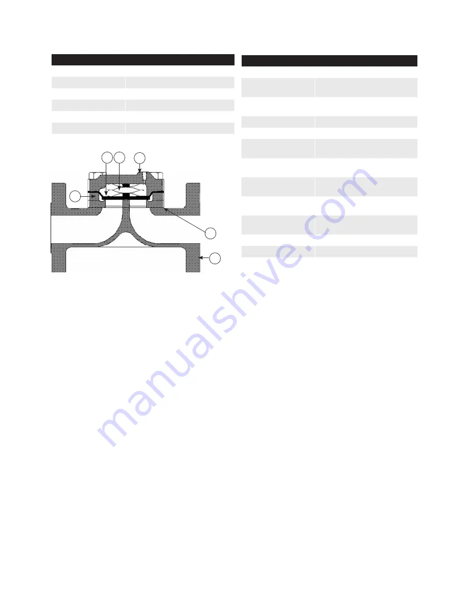
Figure 1 - Flowgrid Parts
All Mooney Flowgrid regulators have six main parts
(excluding bolting and O-rings); the body, throttle plate,
spacer, diaphragm, main spring, and spring case.
Although parts vary in size and design, all regulators
share the same principle of operation.
The
body (1) is constructed with a single port (sizes
less than 10”) and a dual port (sizes greater than 10”).
The dual port design can provide redundant control if
equipped with dual pilots or be used with a single pilot
for maximum capacity.
The
throttle plate (2) supports the diaphragm and
provides a machined surface that the diaphragm seals
against for bubble tight shutoff. Restricted capacity
plates of 35%, 50%, and 75% are available.
The
spacer (3) creates a space between the throttle
plate and the diaphragm which forms a flow path
inside the regulator.
3
1
4
2
5
6
The
fabric-reinforced diaphragm (4) is the main
working part of the Flowgrid regulator. The diaphragm
functions as both an actuator and the regulator
throttling element.
It is designed to provide stability, rangeability, and
fast response without stretching. It will not “take a set”
and is thick for durability and wear resistance.
The
main spring (5) provides high frequency response,
proportional action for stability and a consistent
minimum differential regardless of temperature.
It also provides a positive closing force, which is
important in monitor regulation applications.
The
spring case (6) is shaped to retain the main spring.
It provides a low volume cavity where loading pressure
from the pilot system is placed on top of the diaphragm
to control flow through the regulator.


