MDS 05-6399A01, Rev. E
MDS™ Master Station
101
Earth Curvature
As the distance of a communication link increases, the clearance problem is compounded by the
earth’s curvature. Radio waves traveling through typical atmospheric conditions bend slightly,
which is represented by treating the earth as though it were slightly flatter than it actually is. Ex-
perience has shown that if we consider the earth’s radius 4/3rds of its actual size, we get good
agreement between theory and measured propagation results.
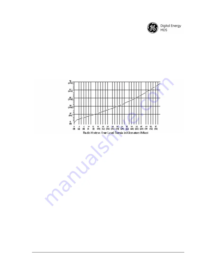
The figure below
shows a representation of the 4/3 earth “radio horizon.” This figure shows that
under normal radio propagation conditions, a station with its antenna 15 meters above flat terrain
will have a radio horizon approximately 15 kilometers away, well beyond the visual horizon.
Figure 8-2. Antenna Height vs. Theoretical Radio Horizon
Fade Margins
Variations in the temperature and humidity of the atmosphere with elevation cause the signals to
bend more or less, resulting in fading at the receiver. The longer the path, the more likely that
deep fades will occur, hence the greater the fade margin required.
Different parts of the world have differing propagation conditions, which can be categorized as
favorable, average, or adverse. In general, mountainous areas have favorable propagation condi-
tions, while tropical areas and those near large bodies of water have adverse conditions.
Calculating Path Loss
Assuming that we have satisfied the line-of-sight and first Fresnel zone clearance requirements,
we can calculate the path loss. At 450 MHz, the loss between two isotropic radiators (0 dBi an-
tennas) that are 1 km apart is 86 dB. For every doubling of distance, the loss increases by an ad-
ditional 6 dB. Knowing this, the output power (+37 dBm), and the receiver sensitivity, we can
calculate antenna size and tower height requirements to cover any desired distance.
Formulas for System Planning
The following standard formulas are provided for assistance in determining system installation
parameters.
Free Space Path Loss
where:
α
fs
= free space loss in dB
d = path distance in kilometers
α
f s
92.4
20
10
f
log
20
10
d
log
+
+
=
Содержание MDS 4710M
Страница 2: ......
Страница 4: ......
Страница 102: ...98 MDS Master Station MDS 05 6399A01 Rev E Remove four screws to remove the duplexer assembly from the tray ...
Страница 113: ......


