8 | GE Oil & Gas
© 2016 General Electric Company. All rights reserved.
4.3 Installation
4.3.1 Positioning
All 173-50 regulators must be installed with the actuator facing
upwards and the diaphragm horizontal.
4.3.2
Installation Diagrams
In most cases the flow crosses the regulator as shown by the
arrow in Figures 9 and 10.
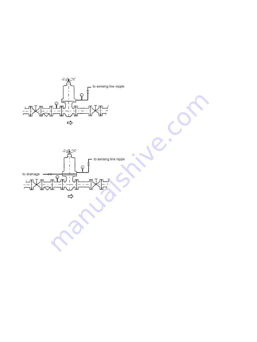
The installation diagrams are therefore as follows:
Figure 11
Example of installation layout for 173-50 single diaphragm
regulators
Figure 12
Example of installation layout for 173-50 double diaphragm
regulators
4.3.3 Isolation Valves and Filter/Pressure Gauges
Install an isolation valve upstream, downstream and on the
sensing and discharge line connection piping, in order to service
the regulator (if necessary) while the plant is pressurized.
Install one filter or pressure gauge upstream from the regulator
and another one on the sensing line connection (as shown in
Figures 11 and 12) in order to calibrate the differential pressure
and keep it constantly under control.
4.3.4 Contamination
Prior to installing the regulator in the piping, make sure the inside
of the pipes are clean and free of any debris (machining cuttings,
weld slag, etc.), especially the upstream section; blow down the
piping if possible to eliminate any remaining dirt: small drops of
weld slag may seriously damage the regulator.
4.3.5 Double Diaphragm Discharge Venting
In double diaphragm regulators, the chamber between the two
diaphragms must be connected to piping to vent the discharge
to a suitable place, safely and constantly at atmospheric
pressure. This hole can be closed with a plug or pressure gauge
with an electrical contact for the remote signaling that the
diaphragm has broken, as long as the downstream plant is
protected (as shown in Figure 12).
4.3.6 Safety Relief
If there is any chance that an overflow regulator failure could
cause the pressure upstream from the reduction regulator to
exceed the maximum admissible pressure for the installation,
a safety relief valve must be installed upstream – without an
isolation valve in between – in order to discharge the entire flow
crossing the differential pressure regulator.
4.3.7 Pressure Drops
Because the regulated pressure sensing port is located inside
the regulator, the pressure drops in the inter-connecting piping
between the regulator and the point of use will affect the
accuracy of the maintained set pressure. This pressure drop
must be considered when calculating the size of the connection.
4.3.8 Pressure Variation
When it is essential to avoid pressure variations at the point
of use, the regulators are fitted with an external sensing line
connection that replaces the internal connection and is fitted
to the lower flange of the actuator. This connection must be
connected as near as possible to the point of use where the
installation of a pressure gauge is also recommended.
4.4 Startup and Calibration
(Refer to Figures 9 and 10)
4.4.1 Pressure Difference
This operation is similar for both single diaphragm and double
diaphragm regulators. The sensing line connection regulator and
the upstream and downstream isolation valves must be closed.
Slightly open the downstream valve and then the upstream
valve together with the sensing line connection, making sure
that the pressure difference read on the pressure gauges is
correct. If necessary, to reduce the pressure difference, turn the
adjustment screw (18) clockwise to increase differential pressure
and counterclockwise to decrease.
4.1.2 Calibration
When the required value is reached, fully open all the valves.
When the downstream system is working at full power, calibrate
by adjusting the screw (18).
4.5 Maintenance
(Refer to Figures 9 and 10)
4.5.1 Maintenance Interval
The required maintenance interval will vary depending on
application. The user must establish a suitable maintenance
schedule depending on the operating conditions. Prior to
disassembly, remove all system pressure from the regulator.
Before starting the above operation, make sure the recommended
spare parts are available (See the parts listed in Figures 9 and 10).


