66 2042376-001 Rev G ©2012 General Electric Company. All rights reserved. Lullaby
TM
Warmer
7.1.6
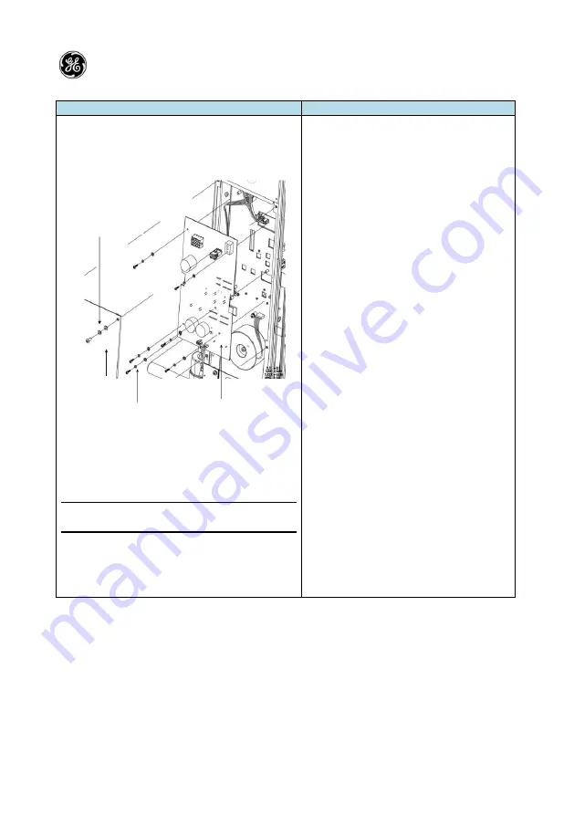
Replacing the PCB Wire Assembly (PWA) (FRU Kit No. 2043951-001)
Illustration
Description
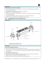
Figure 86:
Replacing Lullaby
TM
Warmer PWA
NOTE: For Warmer with halogen lamp and
transformer
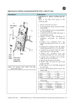
Instructions to replace Lullaby
TM
Warmer
PWA:
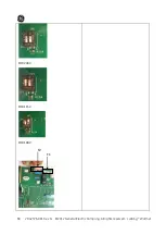
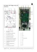
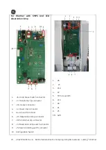
Refer to the PWA PCB Layout in the
following page.
1.
Remove the pillar rear cover.
2.
Disengage all the cable connectors.
Refer to Figure 80.
3.
Remove PWA by unscrewing fasteners
M3 pan head (Qty 6).
4.
Replace with new PWA and secure it
with fasteners (Qty 6).
5.
Engage all the cable assemblies to
respective connectors as explained
below:
Connect the connector from the
observation lamp switch P1 to J1 on
the PWA.
Connect the connector from the Power
ON/standby switch P5 to J5 on the
PWA.
Connect the connector from the power
inlet cable P2 to J2 on the PWA.
Connect the connector from the
observation lamp P13 to J13 on the
PWA.
Connect the connector from Heater
cable P10 to J10 on the PWA.
Swivel switches P6 to J6 on PWA.
Heater earth G4 with M3 pan head
screw on PWA.
Config. plug P9 to J9 on PWA.
Transformer input P7 to J7 and output
P8 to J8 on PWA
6.
Fix back the pillar cover.
PWA
M3x12 Pan Cross
Recs Screw and
Washers
Pillar
Rear
Cover
M5 button
head
Содержание Lullaby Warmer
Страница 12: ...This page is left blank intentionally ...
Страница 138: ...112 2042376 001 Rev G 2012 General Electric Company All rights reserved LullabyTM Warmer Hood Assembly Continued ...
Страница 139: ...LullabyTM Warmer 2042376 001 Rev G 2012 General Electric Company All rights reserved 113 ...
Страница 140: ...114 2042376 001 Rev G 2012 General Electric Company All rights reserved LullabyTM Warmer ...
Страница 150: ...124 2042376 001 Rev G 2012 General Electric Company All rights reserved LullabyTM Warmer ...

