34
The figure below shows the recommended
installation relationship of the ranges to the
vertical walls of the surrounding structure.
Please note the following:
NOTE:
1.
The back of the range may be installed
directly against the rear wall of the structure.
2.
These ranges conform to UL requirements for
“0” spacing from the range to adjacent vertical
walls above the countertop level. However, to
reduce possible scorching of vertical walls and to
minimize potential fire hazards under abnormal
surface unit use conditions such as high heat or
no pans, a minimum of 2
″
spacing should be
provided on both sides of the cooktop.
3.
To eliminate the hazard of reaching over
heated surface units, cabinet storage space
located above the surface units should be
avoided. If a cabinet is to be provided, the
hazard can be reduced by installing a range
hood that projects horizontally a minimum of 5
″
beyond the bottom of the cabinets.
NOTE:
There is a minimum 5
″
clearance
required from the left side of the range to a wall.
This clearance is needed to open the left side
oven door or to remove the left oven shelf.
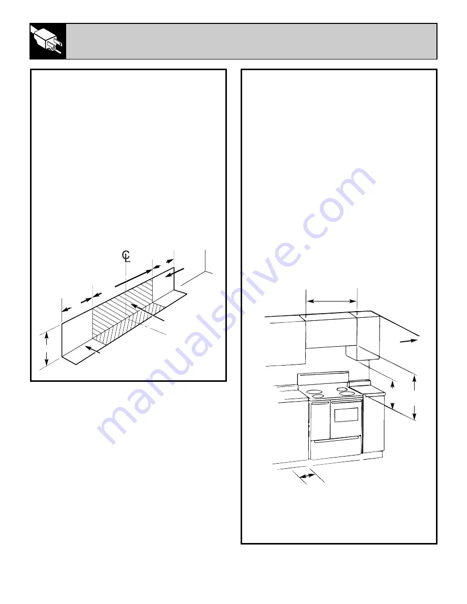
GENERAL
To eliminate the hazard of reaching over heated
surface elements, cabinets or storage spaces
should not be provided over a range.
If cabinets are provided, the hazard can be
reduced by installing a range hood that projects
horizontally a minimum of 5
″
beyond the bottom
of the cabinets.
When installing the range between base cabinets,
refer to figure below for the size of the opening
needed. Do not seal the range to cabinets.
CAUTION:
When unpacking the range, do not
discard the 4 shipping bolts as these are the
leveling legs.
If a service cord is used, the wall receptacle
should be located in accordance with the
dimensions below.
Of Range
Locate outlet in
shaded area
Floor
Wall
10
″
10
″
7
″
max
20
″
Not less than
width of range
Divided cooktop
(40
″
range)
Wall
5
″
Min.
15
″
Min.
30
″
Min.
INSTALLATION INSTRUCTIONS
(continued)
Содержание JCP67
Страница 39: ...38 NOTES ...


