31
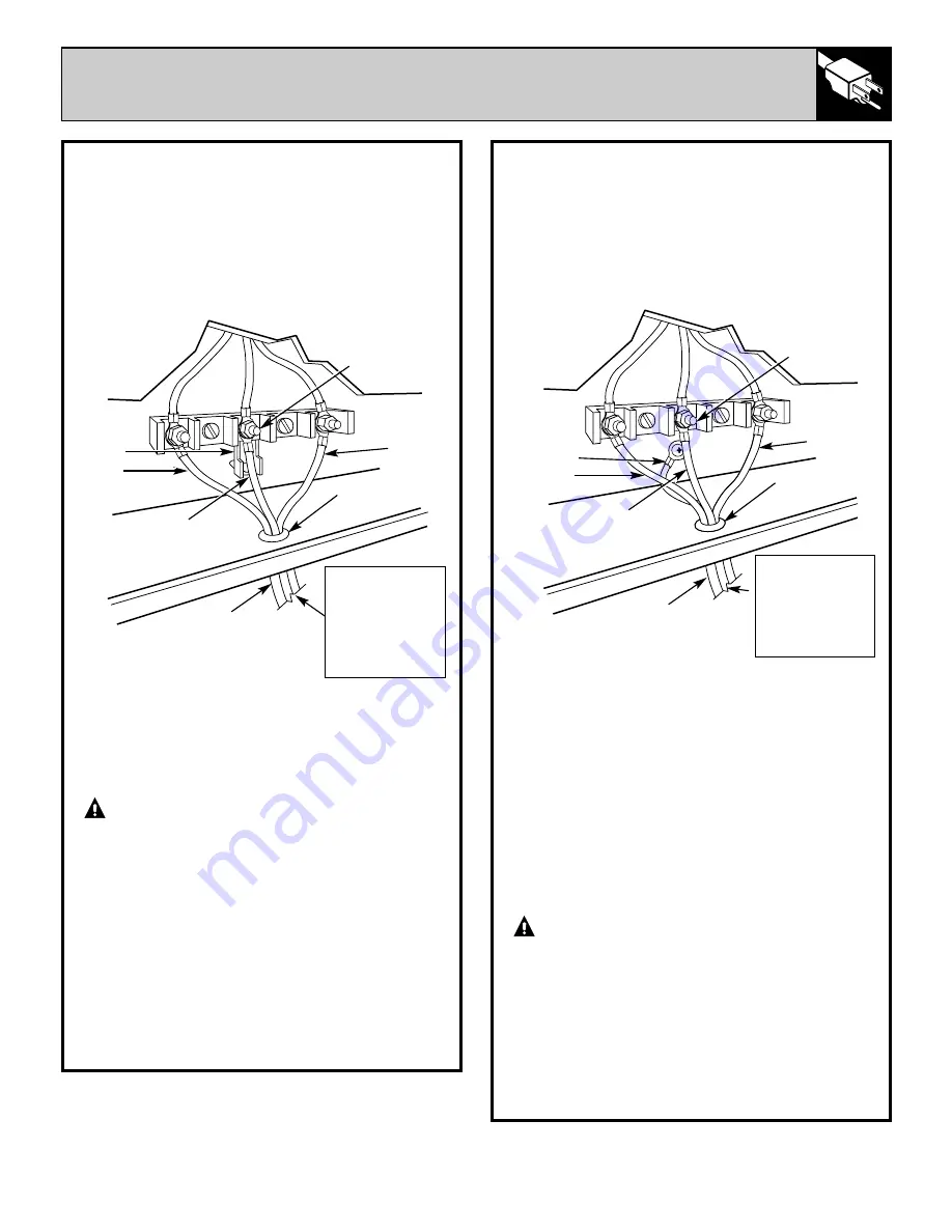
4-WIRE POWER CORD INSTALLATION
WARNING:
The neutral or ground
wire of the power cord must be connected to
the neutral terminal located in the center of
the terminal block. The power leads must be
connected to the left and right terminals of the
terminal block.
A.
Remove the screws and raise the terminal
block cover (lower part of the back wire cover).
B.
Remove the ground strap from the terminal
block and from the appliance frame. Retain the
ground screw.
C.
Connect the ground wire (green) of the
copper power supply cord to the frame of the
appliance. Insert the ground screw into the
power cord ground wire terminal ring and into
the frame of the range. See Figure 2.
D.
Remove the three outer terminal nuts from
the terminal block.
WARNING:
DO NOT loosen any
of the inside nuts on the terminal block.
Electrical failure, loss of electrical connection,
electrical shock or fire may result causing
property damage, personal injury or death.
E.
Connect the neutral (white) wire of the
copper power supply cord to the center silver
colored terminal of the terminal block and
connect the other wires to the outer terminals.
F.
Replace the terminal block cover.
3-WIRE POWER CORD INSTALLATION
WARNING:
The neutral or ground
wire of the power cord must be connected
to the neutral terminal located in the center
of the terminal block. The power leads
must be connected to the left and right
terminals of the terminal block.
A.
Remove the screws and raise the terminal
block cover (lower part of the back wire cover).
B.
Remove the three outer terminal nuts from
the terminal block.
WARNING:
DO NOT loosen any
of the inside nuts on the terminal block.
Electrical failure, loss of electrical
connection, electrical shock or fire may
result causing property damage, personal
injur y or death.
C.
Connect the neutral wire of the copper power
supply cord to the center silver colored terminal
of the terminal block and connect the outer wires
to the outer terminals. See Figure 1.
Ring type terminals must be used on copper
power supply cord wires.
D.
Replace the terminal block cover.
FIGURE 1
Silver colored
terminal
Strain relief
Line 2
Line 1
Ground
strap
Neutral
(white or center)
Copper power
supply cord
(40 Amps)
TO FUSED
DISCONNECT BOX
OR APPROVED
WIRING DEVICE
FOR COPPER
POWER SUPPLY
CORD.
FIGURE 2
Silver colored
terminal
Strain relief
Line 1
No. 8
green
insulated
copper
ground wire
Neutral
(white or center)
4 Wire copper
power supply cord
(40 Amps)
Line 2
TO FUSED
DISCONNECT BOX
OR APPROVED
WIRING DEVICE
FOR COPPER
POWER SUPPLY
CORD.
(continued next page)
Содержание JCP67
Страница 39: ...38 NOTES ...


