GEK-86105
position. The core
has
been factory set to obtain
80%
dropout at the m1n1mum
setting, and a
pp
r
o
x
i
m
ate
l
y 90%
dropout at the maximum setting. To change the
d
ro
p
o
u
t
setting, the
sleeve
(C)
to
which the shading ring
(
D
)
is a
tt
a
c
h
ed
must
always be turned in the clockwise direction (top
view).
This
wil l
prevent
the
sleeve and
s
h
a
d
i
n
g
ring assembly from being
loosened.
When s
hi
pp
e
d
from the
factory, the whole coil is wired into the current circuit,
and t
h
e
lower half of the
cal
ib
r
a
t
i
on
range is available.
If
the
up
pe
r half
of
t
h
e
calibr·ation range
is
required, the tapped
s
e
c
t
i
on of the coil should
be
wi
r
e
d into the current circuit.
Do thi
s
by
ta
king
the
black lead off stud 6 and
the
green lead off stud 6A. Then
put
the gren lead on
stud 6
and
t
h
e black lead on stud 6A
(see
Figure
9).
The unit will pick up at the scale pl
at
e
m
ark
i
n
g
..:!:
5%
with gradually applied
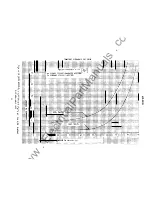
current. Figure 10 shows the transient overreach characteristics. Burden data for
the
60 hertz high dropout unit is tabulated in
Table
IX.
RANGE
AMPERES
1
4
2
8
4 - 16
7
- 28
10 - 40
20 - 80
TABLE IX
BURDEN OF 60 HERTZ HIGH DROPOUT INSTANTANEOUS UNIT
BURDEN AT MINIMUM PICKUP
SETTING AND MINIMUM CURRENT
R OHMS X OHMS Z OHMS
3.16
0.79
0.2
0.07
0.03
0.007
3.16
0.79
0.2
0.07
0.03
0.007
4.48
1.12
0.28
0.1
0.04
0.01
VOLT-AMPERES AT FIVE AMPERES
CALCULATED FROM INPUT AT
MINIMUM PICKUP I2Z
112.0
28.0
7.0
2.50
1.00
0.25
CONSTRUCTION
The IAC66M
r elay
is
mounted in an Ml case that does not
h ave
an upper contact block.
The case
is
su
i
t
a
b
l
e
for either semi-flush or surface mounting on panels up to two
inches
thick.
Hardware is
available
for
al1 panel thicknesses. To be sure that the
proper hardware will be provided, panel thickness should be specified on
the
or
de
r
for the relay. Outline and panel drilling dimensions are shown in Figure 3.
The relay components are mounted
on a
cradle
assembly that can
e
a
s
il
y
be
removed
frorr the relay case.
The cradle is
locked in
the case by
l
a
t
c
h
e
s
at
the top and
bottom.
Electrical
connections
between
case
and cradle
blocks
are c
o
mp
l
et
e
d
th
ro
u
gh
removable
connection
p
l
u
g
s
.
Separate
testing
plugs
can
be
inserted
in
place
of
the
connectior
plugs to
test
the
relay
in i
t
s
case. The cover
is attached to
the
case
from the front,
and
includes an interlock
arm that
p
rev
ent
s
the cover
from
being
replaced
until
the connection plug
has
been inserted.
The
induction
unit, consisting of
a
U-magnet, drag
m
a
g
n
e
t
and
a disk
assembly, is
m
o
unt
ed
on a
m
eta
l frame.
The pickup of the induction unit is
set
by a
ta
p
block
located near the middle
of
t
h
e
relay.
The time delay is adjusted by
turning the
molded
time
dial, located just below the ta
p
b
l
o
c
k
.
The
standard
instantaneous
unit is
m
o
u
n
ted just
above
the drag magnet
on the right
hand
s
i d
e
.
The adjustable core can be
r
a
i
s
e
d
or
l
o
w
e
r
ed
to change the pickup
of the
u
n
i
t.
9
www
. ElectricalPartManuals
. com


