– 71 –
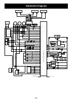
J1-1:
FF thermistor input
J1-2:
Ambient thermistor input
J1-3:
FZ thermistor input
J1-4:
Evaporator thermistor input
J1-5:
+5 VDC output to FF and FZ thermistors
J1-6:
Model ID jumper from J1-5 (18, 24 cu. ft.)
J1-7:
Model ID jumper from J1-5 (26 cu. ft.)
J1-8:
Model ID jumper from J1-5 (24, 26 cu. ft.)
J1-9:
Model ID jumper from J1-5 (18 cu. ft.)
J2-1
: Evaporator fan RPM feedback
J2-2:
Open
J3-3:
Fan Common
J2-4:
Evaporator fan speed
J2-5:
Condenser fan speed
J2-6:
Vertical Mullion Heater
J2-7:
Ice Box Fan
J2-8:
+13.6 VDC (Ice Box Fan, Heaters, and
Lower FF LEDs)
J3-1:
Damper motor
J3-2:
Damper Motor
J3-3:
Damper motor
J3-4:
Damper motor
J3-5:
FZ LED
J3-6 through 10:
Open
J4-1:
GEA Bus - Communications
J4-2:
+13.6 VDC
J4-3:
Board DC Ground
J4-4:
+13.6 VDC
J4-5:
GEA2 Bus - Communications
J5-1
: LEDs
J5-2:
Open
J5-3:
Fill Tube Heater and Recess Heater
J5-4:
Open
J5-5:
+5 VDC output to Ambient, Evap
thermistors, and Humidity Sensor
J5-6:
Humidity Sensor
J6:
Not Used
J7-1:
Auger motor
J7-2:
Auger motor (direction signal for cubed)
J7-3:
Dispenser Water Valve
J7-4:
Auger Line in
J7-5:
Open
J7-6:
Fresh Food door open 120 VAC input
J7-7:
Freezer drawer open 120 VAC input
J7-9:
VAC neutral
J10:
Chassis ground (line noise)
J12:
120 VAC output to Duct Door Heater
J13:
Not used
J14-1:
Ice Box thermistor input
J14-2:
Open
J14-3:
Open
J14-4:
Common
J15-1
: Open
J15-2:
Open
J16:
Not used
J17:
Not used
J18:
Water Detection Signal
J19-1:
120 VAC output to Compressor
J19-2:
120 VAC output to defrost heater
J19-3:
120 VAC supply
J20:
Not used
Connector Locations (continued)
Содержание GFE24JBL
Страница 8: ... 8 Schematic Diagram 86 Index 87 ...


