
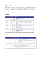
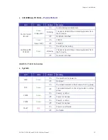
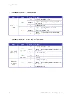


Chapter 2: Installation
GE-DSH-73/DSH-82 and DSH-82-PoE User Manual
27
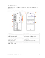
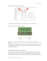
Figure 2-14
:
Wiring the redundant power inputs
3. Tighten the wire-clamp screws to prevent the wires from coming loose.
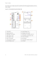
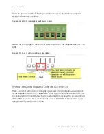
Figure 2-15
:
Wiring the redundant power inputs
1 2 3 4 5 6
Power 2
Power 1
- + - +
NOTE:
The wire gauge for the terminal block should be in the range between 12 ~ 24
AWG.
For the GE-DSH-82-PoE, A 48VDC, 3A power input is required for full PoE load on the
PoE. Please connect an external power source to the terminal block that can supply
steady power at 48VDC.
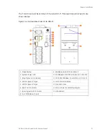
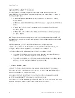
Wiring the Fault Alarm Contact
The fault alarm contacts are in the middle of the terminal block connector as the
picture shows below. Inserting the wires, the Industrial Switch will detect the fault
status of the power failure, or port link failure (available for managed model) and then
Содержание GE-DSH-73
Страница 1: ...GE Security P N 1069172 REV 1 0 ISS 22FEB10 GE DSH 73 DSH 82 DSH 82 PoE User Manual ...
Страница 14: ...Chapter 1 Introduction 10 GE DSH 73 DSH 82 and DSH 82 PoE User Manual ...
Страница 46: ...Chapter 4 Console Management 42 GE DSH 73 DSH 82 and DSH 82 PoE User Manual ...
Страница 166: ...Chapter 6 Command Sets 162 GE DSH 73 DSH 82 and DSH 82 PoE User Manual ...
Страница 178: ... RJ 45 Pin Assignment 174 GE DSH 73 DSH 82 and DSH 82 PoE User Manual ...


