GE Evolve Скачать руководство пользователя страница 2

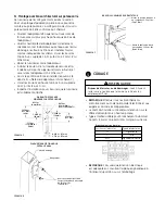
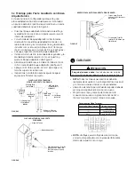
3b   Round Pole Architectural Arm Mounting

This luminaire has been configured specifically to mount 
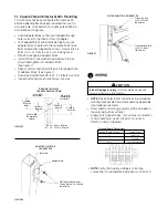
to round pole 3.5-4.5 inches (89-114mm) in diameter.  Hole 
pattern on round pole shall be in  accordance with Figure 2.

WARNING

Under no conditions should architectural  arm mounting bolts 

be torqued to greater than 32 ft-lbs. (43 N-m)

• Place fixture against pole.
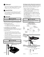
• Install 3/8 bolt, lock washer and washer in top as

shown and tighten into nut plate.

• Open arm door and install 3/8 bolt, lock washer and

washer inside arm as shown and tighten into nut
plate.  (See Figure 3 and 4)

• Torque top and bottom bolts to 25 - 32 ft-lbs (34-43 N-m).
• Inspect installation to ensure fixture is secure.

MOUNTING

3

Follow the appropriate installation instructions based on 
your selected mounting method:

a. Slipfitter Mounting
b. Round Pole Architectural Arm Mounting
c. Square Pole Architectural Arm Mounting

3a  Slipfitter Mounting

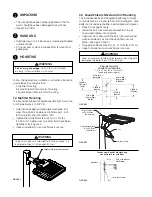
This luminaire has been configured specifically to mount to a 
2-inch pipe brackets (2-3/8” OD)

.

• Hold luminaire approximately level with pipe.  Pull

wires through arm and place slip fitter over 2-inch
(51mm) pipe (2 3/8-inch (60mm) OD).

• Tighten the (4) slipfitter 3/8 bolts to 10-14 ft-lbs

(14-19 N-m).  Tighten jam nuts after bolts have been
tightened.  (See Figure 1)

• Inspect installation to ensure fixture is secure.

WARNING

Risk of injury or damage.  Unit will fall if not installed 

 properly.  Follow installation instructions.

hANDLING

2

• This luminaire has been properly packed so that no

parts should have been damaged during transit.

• Inspect to confirm.

• Damage may occur if luminaire is improperly handled

outside of pack.

• Do not impact or stack luminaire after removal from

packaging.

UNPACKING

1

WARNING

Under no conditions should slipfitter bolts be torqued to a 

level greater than 14 foot pounds (19 N-m).

Slipfitter 3/8 Bolts and Jam Nuts

FIGURE 1

FIGURE 3

Torque Top Bolt

to 25-32 ft-lbs.

(34-43N-m)

Torque Bottom Bolt

to 25-32 ft-lbs.

(34-43N-m)

Door

Arm Door Screw

Section view: Round Pole Mounting

Architectural Arm with Door

FIGURE 4

Nut Plate

Pole

Bolt, Lock Washer, 

Flat Washer

Arm Door Screw

DRILLING TEMPLATE

ROUND POLE MOUNTING

3.5 to 4.5 inch (89 to 114mm) OD

round pole mounting arm.

FIGURE 2

.750 in. DIA.

(19 mm DIA.)

(hOLE)

.438 in. DIA.

(11 mm DIA.)

(2 PLACES)

5.2500 in.

(133 mm)

(MIN.)

1.8120 in.

(46 mm)

2.7190 in.

(69 mm)

5.4380 in.

(138 mm)

.312 in. DIA.

(8 mm DIA.)

Содержание Evolve

Страница 1: ... injury or damage Unit will fall if not installed properly Follow installation instructions WARNING Risk of fire Use supply wire specified on nameplate This device complies with Part 15 of the FCC Rules Operation is subject to thefollowing two conditions 1 This device may not cause harmful interference and 2 this device must accept any interference received including interference that may cause un...

Страница 2: ... place slip fitter over 2 inch 51mm pipe 2 3 8 inch 60mm OD Tighten the 4 slipfitter 3 8 bolts to 10 14 ft lbs 14 19 N m Tighten jam nuts after bolts have been tightened See Figure 1 Inspect installation to ensure fixture is secure WARNING Risk of injury or damage Unit will fall if not installed properly Follow installation instructions handling 2 This luminaire has been properly packed so that no...

Страница 3: ...n accordance with the National Electrical Code and any applicable local code requirements Strain relief for incoming power must be provided in the pole top by the customer Supply Wire Type and Size for Customer Connection to Terminal Board 16 AWG 1 5mm2 to 6 AWG 10mm2 Solid or Stranded wiring 4 CAUTION Risk of Damage or Injury Door should be closed with screw until fixture in final location DRILLI...

Страница 4: ... sensor is shipped with a default program which may be modified using the button on the sensor The sensor has a separate set of instructions on programming which is included PE Dimming Control If Applicable No external connections for Dimming are required when the GE Dimming PE Control and GE Dimming PE Receptacle is used All dimming control connections will be made between the Dimming PE and Lumi...

Страница 5: ... et l entretien la réparation Risque de blessures ou de dommages L appareil tombera s il n est pas installé correctement Suivre les instructions d installation Risque d incendie Utiliser le câble d alimentation indiqué sur la plaque signalétique Cet appareil est conforme à la section 15 des règlementations de la FCC Son fonctionnement est soumis aux deux conditions suivantes 1 Cet appareil ne doit...

Страница 6: ... de 10 14 pi Lbs 14 19 N m Serrer les contre écrous après que les boulons aient été vissés Voir Illustration 1 Inspecter l installation pour s assurer que le luminaire est solidement attaché AVERTISSEMENT AVERTISSEMENT Risque de blessures ou de dommages L appareil tombera s il n est pas installé correctement Suivre les instructions d installation MANUTENTION 2 Ce luminaire a été soigneusement emba...

Страница 7: ...ARQUE Effectuer tous les branchements conformément au Code national de l électricité et aux exigences du code local applicables Le client doit installer un réducteur de tension sur le câble d alimentation en haut du poteau Type et taille du câble pour branchement au bornier 16 AWG 1 5mm2 à 6 AWG 10mm2 plein ou tressé CÂBLAGE 4 MISE EN GARDE Risques de blessures ou de dommages Le portillon doit res...

Страница 8: ...ésence en option Le détecteur de présence programmable est expédié avec un programme par défaut lequel est modifiable via le bouton situé sur le détecteur Le détecteur est fourni avec des instructions de pro grammation séparées Consulter les instructions fournies avec la commande PE de gradation GE concernant les réglages à effectuer pour la commande de gradation d intensité lumineuse Commande de ...

Страница 9: ...TENCIA ADVERTENCIA ADVERTENCIA Riesgo de lesión o daño La unidad caerá si no es instalada adecuadamente Siga las instrucciones de instalación Riesgo de incendio Use los cables de suministro especificados en la placa de fabricante Este aparato cumple con la Parte 15 de las reglas FCC Su oper ación está sujeta a las siguientes dos condiciones 1 Este aparato no puede causar interferencia perjudicial ...

Страница 10: ...0 14 libras pie 14 19 N m Apriete las tuercas después que los tornillos hayan sido apretados Vea figura 1 Inspeccione la instalación para asegurarse que el equipo está firmemente sujeto Riesgo de lesión o daño La unidad caerá si no es instalada adecuadamente Siga las instrucciones de instalación MANEJO 2 Esta luminaria ha sido empacada adecuadamente para que ninguna parte se dañe durante su envío ...

Страница 11: ...nes eléctricas deberán realizarse de acuerdo con el Código Eléctrico Nacional y conforme a códigos locales correspondientes Liberación de tensión para la fuente de poder debe de ser proporcionada en el poste por el usuario Proporcione el tipo y tamaño de cable para la conexión del usuario a la placa terminal 16 AWG 1 5mm2 a 6 AWG 10mm2 Sólido o trenzado CABLEADO 4 PRECAUCIÓN Riesgo de lesiones o d...

Страница 12: ...programable se envía con un programa estándar el cual puede ser modificado usando el botón en el sensor El sensor tiene incluido un set de instrucciones de programación por separado Control Regulador de Intensidad PE Si aplica Ninguna conexión externa para regular la intensidad son requeridas cuando el Control Regulador de Intensidad PE de GE y el Receptáculo del Regulador de Intensidad PE de GE s...

Отзывы: