Installation
1-13
March 2008
Wiring the Foundation
Fieldbus Network
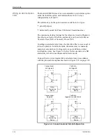
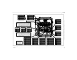
Fieldbus network connections are made at J8/J9, pins 1 and 2 (see
Figure 1-5 below). Optionally, a shield can be connected to J8/J9
pin 3, depending on the network wiring. Connector J8 or J9 will be
installed depending on the option ordered by the customer.
No connections are made to J8/J9, pins 7 and 9, under normal
operation. If it is desired to reset the network board to factory
defaults:
1.
Connect a jumper between J8/J9 pin 7 and pin 9.
2.
Power cycle the instrument.
3.
Ten seconds after the power has been restored to the unit, remove
the jumper to return the network board to normal operation.
Figure 1-5: Network Connections - Standard Option Interior
1
9
J8
1
9
J9
Содержание DigitalFlow GS868
Страница 6: ...Chapter 1...
Страница 28: ...Chapter 2...
Страница 40: ...Chapter 3...
Страница 41: ...Operation Introduction 3 1 Powering Up 3 2 Using the Display 3 3 Taking Measurements 3 5...
Страница 49: ...Chapter 4...
Страница 50: ...Specifications General 4 1 Electrical 4 2 Operational 4 4 Transducer 4 4 Flowcell 4 5...
Страница 56: ...Appendix A...
Страница 57: ...CE Mark Compliance Introduction A 1 Wiring A 1 External Grounding A 1...
Страница 59: ...Appendix B...
Страница 60: ...Data Records Option Cards Installed B 1 Initial Setup Data B 2...
Страница 64: ...Appendix C...
Страница 65: ...Optional Enclosures Introduction C 1 Rack Mount Enclosure C 1 Rack Mount Wiring C 1 Rack Mount Front Panel C 2...
Страница 71: ...Appendix D...
Страница 72: ...Measuring P and L Dimensions Introduction D 1 Measuring P and L D 1...


