background image


Modifications reserved 

Pagina 90/90 

OPM_SPE_XXX_60K_60K_7GB_V010.doc 

Operatine Manual 

SitePro 60 kVA


13 ANNEX 


13.1  TECHNICAL DATA SHEETS 


Can be found included in the last section and are 
listings of the technical data of the UPS. 


13.2 TECHNICAL DIAGRAMS 


These are included in the last sections and include 
assembly layouts and functional drawings. 


Содержание Digital Energy SitePro 400 VAC CESeries 7

Страница 1: ...01 Operating Manual Uninterruptible Power supply Digital Energy SitePro 60 kVA 400 VAC CE Series 7 Manufactured by GE Digital Energy General Electric Company CH 6595 Riazzino Locarno Switzerland T 41 0 91 850 51 51 F 41 0 91 850 51 44 www gedigitalenergy com ...

Страница 2: ... reserved The information contained in this publication is intended solely for the purposes indicated The present publication and any other documentation supplied with the UPS system is not to be reproduced either in part or in its entirety without the prior written consent of GE The illustrations and plans describing the equipment are intended as general reference only and are not necessarily com...

Страница 3: ...at the use of the SitePro Uninterruptible Power Supply system developed and produced to the highest standards of quality will give you complete satisfaction Please carefully read the Operating Manual It contains all the necessary information about the installation of the UPS Thank you for choosing GE Manufactured by Distributed by Your service contact g GE Digital Energy General Electric Company C...

Страница 4: ...he use of the information contained in this document WARNING SitePro 60 kVA is a product for restricted sales distribution to informed partners Installation restrictions or additional measures may be needed to prevent disturbances We recommend that this manual be kept next to the UPS for future references If any problems are encountered with the procedures contained in this manual please contact y...

Страница 5: ...6 3 4 RECTIFIERS PARALLELED ON THE SAME BATTERY 17 3 5 SERVICE AND TECHNICAL SUPPORT 18 3 6 WARRANTY 18 3 7 RECYCLING AT THE END OF SERVICE LIFE 19 4 INSTALLATION 20 4 1 TRANSPORT 20 4 1 1 Dimensions and weight 20 4 2 DELIVERY 21 4 3 STORAGE 21 4 3 1 Storage of the UPS 21 4 3 2 Storage of Battery 21 4 4 PLACE OF INSTALLATION 22 4 4 1 UPS location 22 4 4 2 Battery location 23 4 5 VENTILATION AND CO...

Страница 6: ...ES 70 8 2 1 Complete Shut Down 71 8 2 2 Maintenance shut down of UPS system 73 8 2 3 Shut down of a single unit UPS in a parallel system 75 9 CUSTOMER INTERFACE 76 9 1 CUSTOMER INTERFACE 76 9 1 1 Serial Port J3 RS232 sub D female 9 pin 77 9 1 2 Serial Port J11 RS232 sub D female 9 pin Option 77 9 1 3 Output signals on voltage free contacts 78 9 1 4 Programmable input free contacts 78 9 1 5 EPO Eme...

Страница 7: ...he sidewalls of the UPS make sure that all earth connections when reassembling are correctly reattached This UPS is intended for use in a controlled indoor environment free of conductive contaminants and protected against animals intrusion WARNING HIGH EARTH LEAKAGE CURRENT Earth connection is essential before connecting to AC input Switching OFF the unit does not isolate the UPS from the mains Do...

Страница 8: ...ery cabinet 2 Tools must have insulated handles and must be insulated so that they will not short battery terminals Do not allow a tool to short between individual or separate battery terminals or to the cabinet or rack Do not lay tools or metal parts on top of the battery and do not lay them where they could fall onto the battery or into the cabinet 3 Install the battery as shown on the drawing p...

Страница 9: ...system when not correctly operated NOTE Warns the user about important operations or procedures described in this manual Safety symbols When the text includes one or more of the following symbols that means exist a potentially hazardous situations Please remind the meaning of each symbol CAUTION Related to all the potentially hazardous situations which may result in injury DANGER OF PARTS ELECTRIC...

Страница 10: ...t supported Rated at 0 9 Power Factor SitePro delivers more real power than other UPS in the market With today s trend toward power factor corrected loads SitePro can support more total Load than any other UPS available allowing you to support a greater number of today s enterprise computing Power Factor Corrected PFC equipment No single point of failure Redundant Parallel Architecture RPA is an e...

Страница 11: ...a three phase AC voltage with constant amplitude and frequency which is completely independent and isolated from the AC input voltage Automatic bypass The automatic bypass consists of a static semiconductor switch SSM Static Switch Module used to provide an uninterrupted transfer of the load from inverter to mains Back feed Protection All SitePro UPS s are equipped with an automatic system for the...

Страница 12: ...ns power is available the Load is normally powered through the Automatic Bypass When the mains voltage is detected out of the prescribed tolerances the Load is automatically transferred to the Inverter When the Mains recovers the Load returns to the Automatic Bypass after a variable time defined by the control unit Fig 3 2 2 1 Energy flow in SEM mode operation The SEM mode can be configured direct...

Страница 13: ...ry low warning occurs on a unit not necessary to support the present load this unit will shut down after a timeout period selectable The Load is shared between the other units As the warning occurs on one unit necessary to support the present load the system starts the stop operation timeout selectable The Load will shut down at the end of the stop operation time period 3 2 4 Mains recovery operat...

Страница 14: ... alarm condition will be initiated A Manual Bypass operator initiated will not be considered as an alarm condition Fig 3 2 5 1 Block diagram Automatic Bypass In case of parallel operation Each unit has its own internal Bypass These units are continuously exchanging information enabling all of the internal Bypass circuits in a parallel system to operate simultaneously If the Inverter of a unit fail...

Страница 15: ...ty Several units can be paralleled in order to achieve output power greater than the maximum power of a single unit The maximum total power shared between the paralleled units is equal to the total installed nominal power In the event of a failure of one unit the power supplied by the UPS system becomes insufficient and the Load will be transferred to the Mains Bypass source Parallel units for red...

Страница 16: ...other modules in order to act or react if necessary adapting to the new conditions 3 3 4 Synchronization All units are identical but one unit is arbitrarily selected as the reference and all the other units synchronize to this unit which in turn synchronizes to the Mains Bypass voltage as long as the latter is within tolerances In case of reference failure another unit in the parallel system is au...

Страница 17: ...ion The installation must be performed only with the UPS system must be completely shut down The AC rectifiers input power 5 must be the same with the right phase rotation for each unit Each rectifier must be set for the same floating DC voltage and the same battery current limitation It is mandatory to install the fuses MCB 7 on each line connecting the rectifiers to the common battery for mainte...

Страница 18: ...g 3 5 1 Identification label The requested data permitting to identify your UPS are marked on the identification label fixed on the front of the cabinet behind the lower front door For fast and efficient technical support please mention the data marked on the identification label 3 6 WARRANTY GE operating through its authorised agents warrants that the standard products will be free of defects in ...

Страница 19: ...cting eco design rules It does not contain CFCs Carbon Fluor Clorid or HCFCs Halogen Carbon Fluor Clorid GE in compliance with environment protection recommends to the User that the UPS equipment at the end of its service life must be recovered conforming to the local applicable regulations WARNING Leads contained in the batteries is a dangerous substance for the environment therefore it must be c...

Страница 20: ... side of the cabinet could be damaged If the UPS has to be lifted by crane use suitable carrying belts taking note of the centre of gravity marked on the package Take all necessary precautions to avoid damage to the cabinet while hoisting the UPS Forklift Crane Fig 4 1 1 UPS cabinets moving NOTE Check for sufficient floor and elevator loading capacity 4 1 1 Dimensions and weight Dimensions SitePro...

Страница 21: ...e room away from chemical substances and with a temperature range not exceeding 25 C 13 F to 55 C 131 F Some important functions of the UPS such as the customized functions are defined by parameters stored in a RAM memory A small backup Battery located on the Control Unit board supplies the RAM If the storage time of the UPS exceeds 1 year these functions should be verified by an authorized Servic...

Страница 22: ...mperature is very important for valve regulated batteries maintenance free Operation at temperatures higher than 77 F 25 C will reduce battery life A single phase power socket should be provided for connection of power tools test equipment or connectivity devices SP_060_S7_UPS disposition_GE_01 Min 400mm 16 500mm 20 200mm 8 Min Min Fig 4 4 1 1 SitePro 60 kVA disposition The UPS cabinet can be posi...

Страница 23: ...mmediately adjacent to the UPS left or right side or remotely from the UPS If the Battery is installed remotely from the UPS a wall mounted DC disconnect device must be installed within line of site to both the UPS and the Battery The optimal room temperature for the Battery is 20 C 68 F to 25 C 77 F The life of valve regulated batteries will be reduced by 50 for each additional 10 C 18 F that the...

Страница 24: ...o not put any object on the top of the cabinet it might obstruct the air flow If the UPS is placed on a raised floor the airflow for UPS cooling should enter from underneath the UPS through the appropriate aperture on the raised floor Air filtration systems could be required when the UPS operates in a dirty environment Contact your Dealer or the nearest Service Centre for appropriate solutions In ...

Страница 25: ...t be mounted in the battery enclosure or cabinet not in contact with metallic parts and the J3 plug must be connected to P1 Power Interface see Section 4 8 3 When the sensor is disconnected the floating voltage is calibrated for temperature 20 C If the battery cabinet is not mounted side by side the UPS the cable connecting the temperature sensor to the UPS should be run in a protective trunk or c...

Страница 26: ... Bypass The same power source is to be used for both bypass supply and rectifier input input F3 Bear in mind that when the mains fuses are opened there is a supply failure to the rectifier as well as to the bypass and manual bypass switch In this case the interconnection links BR1 BR2 and BR3 on the input terminals or bus bars MUST REMAIN CONNECTED Separate input Rectifier Bypass recommended The b...

Страница 27: ...ELCB breakers to protect the input connections consider the high leakage current towards the earth generated by the noise suppression capacitors If these ELCB breakers are strictly necessary we suggest to use the largest type suitable for non linear current and for delayed operation To ensure the circuit selectivity in case of short circuit in the load equipment special care must be taken in choos...

Страница 28: ...INPUT OUTPUT LOAD SP_060_S6_connection_01GB X1 Fig 4 8 1 Power connections enclosure Battery power cables are connected to busbars using M10 bolts X1 terminals max rating 70mm2 Separate input rectifier bypass BR1 BR2 and BR3 must be removed L1 1 Rectifier input L1 L2 1 Rectifier input L2 L3 1 Rectifier input L3 L1 2 Bypass input L1 L2 2 Bypass input L2 L3 2 Bypass input L3 N1 Neutral mains input P...

Страница 29: ...as frequency converter mains input bypass terminals not powered With separate AC inputs following a complete battery discharge the UPS system must be restarted only having the rectifier input terminals powered SitePro 60 kVA SP_060_S7_UPS P1_03 P1 If the power source must be changed locally proceed as follows With the UPS completely switched OFF on the P1 Power Interface remove the Jumpers BR3 and...

Страница 30: ...y is fed from the input mains rectifier see Section 4 8 2 the control panel will be powered ON only after closing the input switch Q4 The lamp B1 BYPASS PHASE OK on P1 Power Interface see Section 4 8 2 for clockwise phase rotation check will stay OFF After closing the output switch Q1 the output will not yet be supplied and the LCD screen displays load off The output bus will be supplied only when...

Страница 31: ...shift allowed between units NOTE It is strongly recommended that no transformers automatic circuit breakers or fuses should be inserted between the unit s output and the Load common bus bars However it is recommended that a disconnection or isolation switch is installed in order to totally isolate a unit if needed Verify that power wiring and control wiring run in separate conduits or cable trays ...

Страница 32: ...ntally damaged or disconnected The standard length of the control bus cable between two parallel unit is 12 m 40 ft Maximal overall length of bus connection between the first and the last unit should not be longer than 84 m 276 ft Verify that control wiring is run in individual separate steel conduit NOTE Under no circumstance should the control bus cable connecting JA 1 2 3 4 5 6 7 and JB 1 2 3 4...

Страница 33: ...1 JP2 JP3 and JP4 MUST BE INSERTED SP_010 300_S6_RPA IM0048_03 P3 P13 P11 JA 2 JB 2 JP2 IM 0048 JP1 JP4 JP3 JA 1 JB 1 JP1 JP2 JP4 JP3 J62 B A J52 Fig 4 9 2 3 Bus connection on intermediate units Intermediate units On the parallel bus PCB P34 IM0048 of the intermediate units of the parallel system the Jumpers JP1 JP2 JP3 e JP4 MUST BE REMOVED NOTE In a parallel system composed of 2 or more units on...

Страница 34: ... made on the front of the electronic module fitted behind the front door SP_010 300_S6_RPA IM0048_04GB P3 P13 Next parallel unit JA JA 2 JA 1 JB 1 JB 2 F JB J52 A J62 B F Fig 4 9 3 2 Front view electronic module on intermediate unit J52 A P13 P2 P3 P11 J62 B SP_010 060_S7_RPA IM0048_02 Fig 4 9 3 3 Internal view electronic module Control bus cables connection Plug the cables JA 1 2 3 4 5 6 7 and JB...

Страница 35: ...uting the bus cables JA and JB inside the UPS cabinet In case one unit should be removed from the parallel system the bus cables JA and JB must be removed from the cabinet without disconnecting them from the metal plate where the sockets JA and JB are located For reliability reasons the cables JA 1 2 3 4 5 6 7 and JB 1 2 3 4 5 6 7 connecting the units should be run in separated protected conduits ...

Страница 36: ...al view with open doors Fig 5 1 1 3 Control Panel 1 Electronic Module J11 Serial port RS232 for IMT protocol option M1 Outlet grids fans P1 Scheda Interfaccia Potenza Power Interface Board P4 Customer Interface Board PA Alimentatore 24 VDC opzione Q1 UPS output switch Q2 Manual bypass switch Q4 Input rectifier switch RC Connectivity Rack SNMP Slot for Advanced SNMP Card option SP_060_S7_Customer i...

Страница 37: ...er test Key to test the control panel LEDs and buzzer Pressing this key causes all the LEDs to light and the buzzer to sound 3 times The push button total off is protected by a red cover By pressing it you immediately separate the UPS from mains and the Load Attention total off cannot disconnect the UPS from the Load with Q2 closed To reset total off push and hold the total off push button and the...

Страница 38: ...nverter will shut down All LEDs ON indicate that the Battery is fully charged LED a Yellow Fixed indicating last 25 of Battery backup Blinking indicating Battery backup 5 LED b c d Green Each one indicating 25 of Battery backup LEDs ON indicate the Load status of the UPS LED d red 100 load LED c yellow 100 load LED b green 66 load LED a green 33 load Fig 6 2 1 LEDs on synoptic diagram LEDs on syno...

Страница 39: ...ering information for the user to be able to examine the operating status at any time alarms In the event of mains failures or abnormal functioning the UPS must keep a history of what has happened as a series of events parameters The user must be able to program certain functions of the UPS user parameters accessible without password to his needs LCD screen standard version LCD screen 4 rows x 20 ...

Страница 40: ...isplays the current status of the UPS in a condensed form The information offered by this screen consists of The type of the machine family name series number P unit number for parallel version from 1 to 8 and power range The status of the load referred to the most loaded phase for RPA respect to the rated power of Parallel System The estimated battery backup time in minutes with the present load ...

Страница 41: ...ier This screen displays I1 output current rectifier bridge I2 output current 2nd rectifier bridge optional 12 pulses rectifier only The voltage levels between the three phases line to line The input frequency of the rectifier RECTIFIER U12 387V Iout1 41A U23 385V Iout2 0A U31 391V f 50 0Hz metering alarms parameters ok Inverter data screen This screen displays The voltage level of the three phase...

Страница 42: ...ses screen 1 This screen displays for each phase The output phase voltage and current as RMS values for RPA total value of Parallel System The output load as percent for RPA respect to the rated power of Parallel System LOAD ON PHASES U1 230V I 72A 80 U2 230V I 45A 50 U3 230V I 75A 80 metering alarms parameters ok Load on phases screen 2 This screen displays for each phase The load active power kW...

Страница 43: ...faults rectifier mains out of tolerance faults The total number of detected output overloads MAINS FAULTS STAT MINOR 43210 MAJOR 11267 Overloads 654 metering alarms parameters ok UPS identification screen This screen displays The UPS family and the power range The software version on control board The serial number UPS IDENTIFICATION SitePro S7 60kVA SW Version x xx S N A7060 1505 0001 metering al...

Страница 44: ...rs mode scrolls forward to the next screen scrolls backward to the previous screen ok display the main screen for this mode The events displayed are the standard GE events as described in the Section 7 7 EVENTS Alarms Messages The information displayed includes The exact date and time when the event occurred The number of the event 255 being the most recent event and 0 the oldest The standard GE c...

Страница 45: ... scroll forward to the next screen scroll forward to the next screen select from the current screen the parameter to edit ok start the editing for the currently selected parameter NOTE During parameters mode it is not possible to scroll back Example of operation within parameters mode Purpose to correct a wrong telephone number previously stored in Tel2 1 Entering parameters mode parameters The fi...

Страница 46: ...Move the selection underscore cursor to the next parameter in this page Tel1 002186394567 Tel1 enabled N Tel2 004017464340 Tel2 enabled N metering 4 alarms parameters ok 5 Move the selection to the next parameter in page Tel1 002186394567 Tel1 enabled N Tel2 004017464340 Tel2 enabled N metering 5 alarms parameters ok 6 Enter EDIT MODE for the currently selected parameter ok EDIT MODE PHONE NUMBER ...

Страница 47: ...larms exits Edit mode and enters Alarms mode any changes are discarded parameters exits Edit mode and enters Parameters mode any changes are discarded scroll from editable position to editable position change the currently selected editable position ok return to Parameters mode after saving the changes Examples of operation during Edit mode There are three types of parameters they differ in behavi...

Страница 48: ...002186394567 Tel1 enabled N Tel2 006017464340 Tel2 enabled N metering 5 alarms parameters ok Type 2 Parameters having a limited range of values For example the parameter Printer Baud Rate has the range 600 1200 2400 4800 and 9600 There is no need to edit this parameter digit by digit By pressing the button the next value within the range is automatically provided by the software 1 Enter Edit mode ...

Страница 49: ...tion the user sets the parameter to Yes 2 The user wants to abort the action the user sets the parameter to No The actions that can be performed using such software buttons are Print the metering information Print the last 256 events Print the values of the parameters Print all the information obtainable from the UPS Returning from the Edit mode Normally the ok button is used to return from the Ed...

Страница 50: ...s parameter The value you enter is thoroughly checked to be a correct time in the format hh mm ss The time is specified in 24 hour format 2 Protocol Set up PROTOCOL SETUP Modem enabled N Init BEQV1X3 D0S0 2 Alarm N Delay 22sec metering alarms parameters ok Modem enabled You can enable disable with Y N the remote control through modem calls by using this parameter Init This parameter presents the m...

Страница 51: ...cond telephone number will be used for dial out Tel3 A third dial out number Tel3 enabled This parameter Y N specifies if the third telephone number will be used for dial out Tel4 A fourth dial out number Tel4 enabled This parameter Y N specifies if the fourth telephone number will be used for dial out 4 LCD Display LCD Display UPS NAME SG Series Contrast 9 Language ENGLISH metering alarms paramet...

Страница 52: ...f the data word on the serial line during data transmission 7 or 8 bits are offered as choice Please select 8 bits as this is the only valid value Handshake This parameter is used to determine the communication protocol used when printing Valid values are XON standing for the XON XOFF protocol or NO standing for any protocol Print All This parameter Y N is used to print all the available informati...

Страница 53: ...e intervals are defined by SEM START the hour of the day after which the SEM mode is enabled The SEM mode is enabled until the following SEM STOP time is reached the SEM STOP time of the same day if this is later than the SEM START time the SEM STOP time of the following day otherwise SEM STOP the hour of the day before which the SEM mode is enabled The SEM mode is enabled starting from the preced...

Страница 54: ...eekday d1 Saturday d2 Sunday d3 Monday d4 Tuesday d5 Wednesday d6 Thursday d7 Friday SEM START 00 00 00 00 18 00 18 00 18 00 18 00 18 00 SEM STOP 23 59 23 59 06 00 06 00 06 00 06 00 06 00 Example 4 If the SEM mode must be enabled on Monday d3 and Tuesday d4 between 18 00 in the evening and 06 00 of the following morning on Friday d7 between 12 00 and 13 00 during all Saturday d1 and on Sunday d2 u...

Страница 55: ...time of weekday d3 Monday has no effect as it is followed by the SEM STOP time of weekday d4 Tuesday It can be without change of meaning any time between 18 00 and 23 59 Similarly the SEM mode is active from 18 00 of weekday d4 Tuesday until 06 00 of weekday d5 Wednesday The SEM START time of weekday d5 Wednesday has no effect as it is preceded by the SEM START time of weekday d4 Tuesday It can be...

Страница 56: ...hange the language from the PARAMETERS menu when the language set up screen is displayed The procedure is like for the standard 4 x 20 LCD Metering The screens are displaying the same information as per the standard LCD The information is split in more parts than on the standard LCD For scrolling the screens the and metering keys can be used Alarms The alarms events are described only using the nu...

Страница 57: ...t missing on the communication bus even though switch Q1 is still closed 4104 BATTERY FUSES This function when enabled on input programmable relays password required warns the user about the external battery fuses failure or MCB opening signalled by NO free contact 4106 RECTIFIER TRANSFORMER OVERTEMPERATURE The temperature sensor inside the input transformer winding indicates overtemperature Only ...

Страница 58: ... The Slave oscillator is not in synchrony with the Master thus causing the shutdown of it s inverter If after a restart the condition remains the LED inside the Inverter symbol on the panel will not light up indicating that this inverter cannot supply the load anymore 4404 K6 CLOSING FAILURE K6 open despite a closing command being done Signalled by auxiliary contact The load cannot be supplied by ...

Страница 59: ...cally on inverter when load 100 4581 INVERTER AND MAINS NOT SYNCH The voltages of mains and inverter are not synchronised which causes the opening of K6 4697 BATTERY OVERTEMPERATURE The battery temperature exceeds the value inserted in parameter Disabled with parameter service only 4698 BATTERY POWER INSUFFICIENT In case of mains failure with the actual load the run time would be below Stop operat...

Страница 60: ...ss enabled depends on setting of respective parameter 4302 INVERTER CANNOT BE TURNED ON Inverter cannot be switched on because one of the following conditions is still present Overtemperature Low battery voltage Inverter fuses Overload K7 opening failure High battery voltage DC low EPO 4303 INVERTER CANNOT BE TURNEDOFF Inverter cannot be switched OFF because the load cannot be switched to mains vo...

Страница 61: ...o synchronise with mains has been done for mains BP OK 4411 or setting parameters 4600 COMMAND UPS ON The SEM mode function has been disabled or the programmed time is expired The UPS returns to VFI mode supplying the load normally by inverter 4601 COMMAND UPS STAND BY The function SEM mode is enabled and according to the time program the UPS will run in SEM mode supplying the load normally by mai...

Страница 62: ...S rating kVA Customer Place Date Sent by 1 Record the exact UPS status on the panel when the failure appeared 2 On the LCD panel enter the alarms mode and record the alarms messages in the list below indicating at least 5 events before the failure time Remark exact data and time are very important Event No Event Code UPS Status Date Time h m s 255 254 LED 1 R ON R OFF 253 LED 2 R ON R OFF 252 LED ...

Страница 63: ... from whom the equipment was purchased There are different start up procedures as described on the following pages depending on the configuration and the initial state of the UPS system Initial Start up of UPS single and parallel system This procedure describes how to switch on a single UPS or a complete UPS parallel system Initial start up following the installation means that the load is not bei...

Страница 64: ...ults OK SELF TEST OK will appear on the display The main screen will indicate the status load off Verify set the real clock time refer to Section 7 3 Parameters 2 Check for correct phase rotation of input mains on P1 Power Interface Lamp B1 ON the phase rotation clockwise is correct see Fig 4 8 2 1 Lamp B1 OFF the phase rotation anti clockwise is not correct see Fig 4 8 2 1 In this case switch OFF...

Страница 65: ... blinking and stay fixed lit The load will be automatically transferred from mains to inverter LEDs 1 2 3 4b 5 6 and 8 are now lit LEDs 4a 7 and 9 are OFF The LCD panel must display the main screen indicating the status LOAD ON INVERTER and the value of the battery reserve 7 Load supply Your SitePro UPS is now running supplying power to the output Insert the loads one by one to the output of the U...

Страница 66: ...e check is OFF LEDs 1 2 3 4b 7 and 8 light up LEDs 4a 5 6 and 9 are OFF 6 Inverter start Press the key I on the control panel of the unit no 1 The inverter will start up LED 5 inside inverter symbol must be blinking In a short time as the inverter voltage is confirmed the LED will stop blinking and the output will be automatically transferred from mains to inverter LED 6 becomes ON and LED 7 turns...

Страница 67: ...e rectifier symbol stops blinking and stay ON indicating that the DC link has reached the floating voltage 3 Battery coupling to DC link Close the external battery circuit breaker or battery fuses after checking the right polarity The battery is now connected to the DC link LED 4b should be lit indicating battery charge The buzzer switch OFF and LED alarm is OFF 4 Close the output switch Q1 The lo...

Страница 68: ...nd service check is OFF In case the load off has been previously activated a reset is needed to enable the bypass 5 Now open the maintenance switch Q2 on each unit LED 9 turns OFF when opening the last Q2 Now the control panel of each unit should indicate the following situation LED 1 2 3 4b 7 and 8 light up LED 4a 5 6 and 9 are OFF LED service check is OFF 6 Inverter start Press the key ON on the...

Страница 69: ...ct see Fig 4 8 2 1 Lamp B1 OFF the phase rotation anti clockwise is not correct see Fig 4 8 2 1 In this case switch OFF the mains reverse two phases between them on the line supplying the UPS and repeat the procedure from point 1 LED 2 on the control panel must be lit 3 Close the input switch Q4 LED 1 must be lighted and LED 3 inside rectifier symbol must blink The rectifier starts up automaticall...

Страница 70: ...em Complete Shut Down SitePro single and parallel UPS system The UPS system and the critical load have to be completely powered down Maintenance Shut Down SitePro single and parallel UPS system The UPS system has to be turned OFF while providing the load power by mains through the maintenance bypass switches Q2 Shut down of a single unit SitePro in a parallel system One unit of the redundant paral...

Страница 71: ...cally transferred back to the inverter and the inverter stay ON The LCD display must indicate LOAD ON BYPASS The LEDs 1 2 3 4b 7 and 8 are ON The LEDs 4a 5 6 and 9 are OFF NOTE Before doing the next operation make sure that you have shut down all equipment which is normally powered by the UPS 2 On the control panel press the push button load off protected by the sliding red cover The output contac...

Страница 72: ...5 and 6 turns OFF LED 7 turns ON The LCD display must indicate LOAD ON BYPASS The LEDs 1 2 3 4b 7 and 8 are ON The LEDs 4a 5 6 and 9 are OFF 2 On the control panel press the push button load off protected by the sliding red cover only on one unit connected to the parallel bus The output contactor K6 on each unit open and the UPS output will be powered down 3 Turn the input rectifier switch Q4 OFF ...

Страница 73: ...splay must indicate LOAD ON BYPASS The LEDs 1 2 3 4b 7 and 8 are ON The LEDs 4a 5 6 and 9 are OFF NOTE Not following this procedure can cause protected loads to shut down 2 Close the maintenance switch Q2 LED 9 is now ON The load is now supplied by the mains also through manual bypass 3 Open the output switch Q1 LED service check is ON The load is now supplied only through the manual bypass 4 On t...

Страница 74: ...l the units when closing the first Q2 The load is now supplied by the mains also through all the manual bypass 3 Open the output switch Q1 on each unit LEDs Service check are ON on each unit The load is now supplied only through the manual bypass 4 On the control panel press the push button load off protected by the sliding red cover on all the units of the parallel system The output contactor K6 ...

Страница 75: ...system is not redundant In this case is not possible to switch OFF one unit without transferring the load on mains The LCD display of this unit must indicate LOAD ON INVERTER The LEDs 1 2 3 4b and 8 are ON The LEDs 4a 5 6 7 and 9 are OFF NOTE Not following this procedure can cause protected loads to shut down 2 Open the circuit breaker Q1 only on this unit LED 7 and service check is now lit LED 6 ...

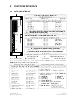
Страница 76: ... 2 14 3 15 4 16 5 17 6 18 7 19 8 20 9 21 10 22 11 1 14 9 1 X1 J2 J3 J5 J4 2 1 JP3 X2 Fig 9 1 1 Customer interface NO Normally Open C Common NC Normally Closed The connectors A J2 and B J3 can be used for additional Advanced SNMP Card or an additional Customer Interface installation only when the UPS is switched Off Output signals on voltage free contacts Programmable functions on input contacts On...

Страница 77: ...J11 RS232 sub D female 9 pin Option SP_060_S7_J11_01 Q4 Q1 Q2 J11 Fig 9 1 2 1 Serial port J11 Total remote management of the system on PC by means of the ARGUS Control Network Software optional This software enables the user to monitor the status of remote UPS from any computer connected to a modem or through a direct link to the UPS Connection of a serial printer From the display panel it is poss...

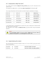
Страница 78: ...4 or J2 14 15 16 NO C NC Load on Mains X1 15 16 17 or J2 17 18 19 NO C NC General Alarm X1 18 19 20 or J2 20 21 22 NO C NC Acoustic Alarm In case different alarms or operating status are required they can be configured on the same terminals via software from the control panel The configuration can be changed in parameters mode by a trained operator using the appropriate password NOTE The programma...

Страница 79: ...3 X2 Fig 9 1 5 1 X2 and J2 for connection EPO NOTE This procedure could imply a load shutdown NOTE To enable this function remove jumper JP3 on the P4 Customer Interface when the cables have already been connected on X2 or J2 In case of parallel Customer Interface up to 3 the EPO contact must be connected to one Customer Interface only but the bridge on X2 and jumper JP3 on the P4 Customer Interfa...

Страница 80: ...nation or delay of Battery recharging during the generator operation In a parallel system a separate NO Normally Open contact must be connected to each individual unit 9 1 7 AUX external Maintenance Bypass If the UPS system is equipped with an external Maintenance Bypass Switch it is possible to connect a NO Normally Open voltage free aux contact from the External Bypass Switch to the programmable...

Страница 81: ... this information to determine the state of the UPS in order to guarantee safe and orderly shutdown of the server when needed IRIS Service Internet Remote Information System Internet Remote Information System for UPS System JUMP Software Suite Java Universal Management Protocol Software application for the control and monitoring of the UPS Mute Test SGT5000_OPT_RMS_01 Stop Alarm g GE Digital Energ...

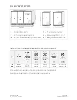
Страница 82: ...nal cabinet 500 mm 12 pulses rectifier with galvanic isolation Located in additional cabinet 500 mm Empty battery cabinets Dimensions W x D x H 750 x 800 x 1450 mm 29 53 x 31 50 x 57 09 inches 1100 x 800 x 1450 mm 43 30 x 31 50 x 57 09 inches Centralised maintenance bypass for RPA configuration Top cable entry box Dimensions W x D x H 100 x 800 x 1450 mm 19 69 x 31 50 x 57 09 inches NOTE Connectio...

Страница 83: ... common configurations UPS standard Rectifier and or bypass transformer in additional cabinet 12 pulses rectifier without galvanic isolation in additional cabinet 12 pulses rectifier with galvanic isolation in additional cabinet Input filter 5th harmonic in additional cabinet Empty Battery Cabinet 4 750 mm 5 1100 mm UPS 1 2 2a 2a 3 4 5 60 kVA 455 kg 1004 lbs 430 kg 948 lbs 285 kg 629 lbs 330 kg 72...

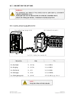
Страница 84: ...riptions Installation described on Section 1 10 5 1 Auxiliary Power Supply APS 24 VDC PA Auxiliary Power Supply 24 VDC XB Terminals for connection PA OPT_APS_SP060 S7_01 XB PA N L NC _ L N M4x10 _ L N Fig 10 5 1 1 Auxiliary Power Supply 24 VDC Connection From To Cable PA black PA APS PA Terminal XB1 Cable PA grey PA APS PA Terminal XB2 Cable PA L black PA APS L Terminal F50 L Cable PA N grey PA AP...

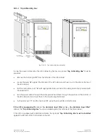
Страница 85: ...ble cover D with appropriate hole and install the cable glands not provided with the equipment Run the power cables through the cable glands feed them through the aperture at the bottom of the UPS cabinet and connect them to the input output terminals Fix the side cover C and the top cover D using the screws fitted on both sides If the UPS is equipped with optional 5th Harmonic Input Filter or 5th...

Страница 86: ...nected on terminals X1 instead J2 see correlation X1 J2 in Section 9 1 GE Digital Energy P4 Customer Interface 31 23 1 3 2 4 5 J2 SUB D MALE B 14 10 8 7 6 9 12 11 13 19 15 16 17 18 21 20 22 16 X3 22 23 19 20 17 g 130mm 5 1 4 in X4 43 55 56 49 50 44 37 40 42 38 33 34 32 25 24 N _ L XB3 XB2 XB1 F50 IM6544 X15 SIGNALLING A 1 2 REMOTE max 300m 985ft 216mm 8 1 2 Mute Test Alarm Stop SP_OPT_060_S7_RSB_0...

Страница 87: ...n in the unit and in the battery We recommend replacement of the fans in the units every 20 000 hours Other components with limited lifetime We recommend the replacement of components such as filter capacitors and lithium battery for the backup of data on the control boards of the units every 50 000 hours Battery We recommend a periodic manual battery test especially if the automatic battery test ...

Страница 88: ...es b Replacement of defective parts or the preventive replacement of parts with a defined life time c Updating of the equipment technical improvements subsequent to the delivery d Check the calibration of DC voltage and Inverter output voltage and frequency e Check of the settings of the electronic regulation the control and the alarm circuits of the rectifier s and inverter s f Functional checks ...

Страница 89: ...doc Operatine Manual SitePro 60 kVA 12NOTES 12 1 NOTES FORM It is recommended to note in this section Notes with date and short description all the operations performed on the UPS as maintenance components replacement abnormal situations etc Date Description Done by ...

Страница 90: ...eratine Manual SitePro 60 kVA 13ANNEX 13 1 TECHNICAL DATA SHEETS Can be found included in the last section and are listings of the technical data of the UPS 13 2 TECHNICAL DIAGRAMS These are included in the last sections and include assembly layouts and functional drawings ...

Отзывы: