


GE Multilin
D30 Line Distance Protection System
4-3
4 HUMAN INTERFACES
4.1 ENERVISTA UR SETUP SOFTWARE INTERFACE
4
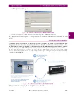
Before backing up settings and upgrading, set the
Settings > Product Setup > Security > Dual Permission Security
Access > Remote Setting Authorized
and
Local Setting Authorized
settings to "ON." Otherwise, the upgrade is blocked
and results in an "Unable to put relay in flash mode" message.
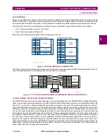
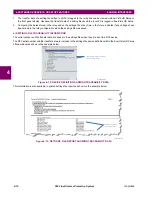
Modbus addresses assigned to firmware modules, features, settings, and corresponding data items (that is, default
values, minimum/maximum values, data type, and item size) can change slightly from version to version of firm-
ware. The addresses are rearranged when new features are added or existing features are enhanced or modified.
The
EEPROM DATA ERROR
message displayed after upgrading/downgrading the firmware is a resettable, self-test
message intended to inform users that the Modbus addresses have changed with the upgraded firmware. This
message does not signal any problems when appearing after firmware upgrades.
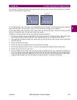
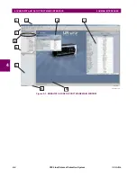
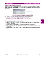
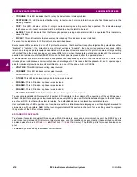
4.1.4 ENERVISTA UR SETUP MAIN WINDOW
The EnerVista UR Setup software main window supports the following primary display components:
1.
Title bar that shows the pathname of the active data view
2.
Main window menu bar
3.
Main window tool bar
4.
Site list control bar window
5.
Settings list control bar window
6.
Device data view windows, with common tool bar
7.
Settings file data view windows, with common tool bar
8.
Workspace area with data view tabs
9.
Status bar
10. Quick action hot links
NOTE
Содержание D30D00HCHF8AH6AM6BP8BX7A
Страница 10: ...x D30 Line Distance Protection System GE Multilin TABLE OF CONTENTS...
Страница 52: ...2 22 D30 Line Distance Protection System GE Multilin 2 2 SPECIFICATIONS 2 PRODUCT DESCRIPTION 2...
Страница 96: ...3 44 D30 Line Distance Protection System GE Multilin 3 3 DIRECT INPUT OUTPUT COMMUNICATIONS 3 HARDWARE 3...
Страница 126: ...4 30 D30 Line Distance Protection System GE Multilin 4 3 FACEPLATE INTERFACE 4 HUMAN INTERFACES 4...
Страница 374: ...5 248 D30 Line Distance Protection System GE Multilin 5 10 TESTING 5 SETTINGS 5...
Страница 398: ...6 24 D30 Line Distance Protection System GE Multilin 6 5 PRODUCT INFORMATION 6 ACTUAL VALUES 6...
Страница 410: ...7 12 D30 Line Distance Protection System GE Multilin 7 2 TARGETS 7 COMMANDS AND TARGETS 7...
Страница 444: ...9 24 D30 Line Distance Protection System GE Multilin 9 5 FAULT LOCATOR 9 THEORY OF OPERATION 9...
Страница 576: ...B 102 D30 Line Distance Protection System GE Multilin B 4 MEMORY MAPPING APPENDIX B B...
Страница 616: ...D 10 D30 Line Distance Protection System GE Multilin D 1 IEC 60870 5 104 PROTOCOL APPENDIX D D...
Страница 628: ...E 12 D30 Line Distance Protection System GE Multilin E 2 DNP POINT LISTS APPENDIX E E...
Страница 636: ...F 8 D30 Line Distance Protection System GE Multilin F 3 WARRANTY APPENDIX F F...
Страница 646: ...x D30 Line Distance Protection System GE Multilin INDEX...


