background image

4

Quick Start

Caution: READ SECTION 6 TITLED BATH USE before placing the bath

in service. Incorrect handling can damage the bath and void the warranty.

This chapter gives a brief summary of the steps required to set up and operate
the bath. This should be used as a general overview and reference and not as a
substitute for the remainder of the manual. Please read Section 5 through 8
carefully before operating the bath.

4.1

Unpacking

Unpack the bath carefully and inspect it for any damage that may have oc-
curred during shipment. If there is shipping damage, notify the carrier immedi-
ately. Verify that all components are present:

CTR –80 Bath

Access Hole Cover

Manual

RS-232 Cable

Report of Test

Drain Valve

4.2

Set-up

Caution: The drain valve must be installed on the back of the bath before

attempting to fill the tank with fluid. See Section 5.3, on page 17 for drain
installation instructions.

Warning: The instrument is equipped with a soft cutout (user settable firm-

ware) and a hard cutout (set at the factory). Check the flash point, boiling
point, or other fluid characteristic applicable to the circumstances of the
unit operation. Ensure that the soft cutout is adjusted to the fluid charac-
teristics of the application. As a guideline, the soft cutout should be set
10°C to 15°C below the flash point of the bath fluid. See Section , Heat
Transfer Fluid, for specific information on bath fluids and Section , Cut-
out.

13

4 Quick Start

Содержание CTR 80

Страница 1: ...GE Kaye CTR 80 Cold Temperature Reference User s Guide ...

Страница 2: ... USA tel 978 262 0005 800 964 5293 US Canada fax 978 439 8181 email kaye ge com European Headquaters GE Kaye Europe Sinsheimer Strasse 6 D 75179 Pforzheim Germany tel 49 0 7231 14335 0 fax 49 0 7231 14335 29 email info kaye europe com www gekaye com Subject to change without notice Copyright 2002 Printed in USA ...

Страница 3: ...nt Warranty 10 3 3 2 In Warranty Repairs 10 3 3 3 After Warranty Repairs 10 3 3 4 Equipment Maintenance Agreements 11 3 3 5 Customer Support 11 3 3 6 Customer Support Agreement 11 3 3 7 Customer Site Assistance 11 4 Quick Start 13 4 1 Unpacking 13 4 2 Set up 13 4 3 Power 14 4 4 Setting the Temperature 14 5 Installation 17 5 1 Bath Environment 17 5 2 Dry out Period 17 5 3 Bath Preparation and Filli...

Страница 4: ...ed Fluids 29 8 1 10 1 Water Distilled 29 8 1 10 2 Ethanol 29 8 1 10 3 Mineral Oil 30 8 1 10 4 Silicone Oil Dow Corning 200 05 200 10 200 20 30 8 1 10 5 Halocarbon 0 8 30 8 1 11 Fluid Characteristics Table 30 8 1 11 1 Limitations and Disclaimer 31 8 2 Stirring 32 8 3 Power 32 8 4 Heater 32 8 5 Refrigeration 32 8 5 1 Operation 33 8 5 2 Important Refrigerant Information 33 8 6 Temperature Controller ...

Страница 5: ... 9 11 2 R0 46 9 11 3 ALPHA 46 9 11 4 DELTA 46 9 11 5 BETA 46 10 Digital Communication Interface 47 10 1 Serial Communications 47 10 1 1 Wiring 48 10 1 2 Setup 48 10 1 2 1 Baud Rate 48 10 1 2 2 Sample Period 49 10 1 2 3 Duplex Mode 49 10 1 2 4 Linefeed 49 10 1 3 Serial Operation 49 10 2 Interface Commands 49 11 Calibration Procedure 53 11 1 Calibration Procedure 53 11 1 1 Calibration Equipment 53 1...

Страница 6: ...13 3 Wiring Diagram 59 iv ...

Страница 7: ...ation IMPORTANT Do Not Over Tighten Follow the installation instructions above 18 Figure 2 CTR 80 Control Panel 23 Figure 3 Back Panel 25 Figure 4 Controller Operation Flowchart 36 Figure 5 Serial Cable Wiring 48 Figure 6 Wiring Diagram 59 ...

Страница 8: ...vi Tables Table 1 International Electrical Symbols 1 Table 2 Table of Various Bath Fluids 31 Table 3 Controller Communications Commands 50 Table 3 Controller Communications Commands continued 51 ...

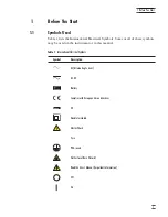
Страница 9: ...used on the instrument or in this manual Symbol Description AC Alternating Current AC DC Battery Complies with European Union directives DC Double Insulated Electric Shock Fuse PE Ground Hot Surface Burn Hazard Read the User s Manual Important Information Off On 1 1 Before You Start Table 1 International Electrical Symbols ...

Страница 10: ...Caution Warning identifies conditions and actions that may pose hazards to the user Caution identifies conditions and actions that may damage the instru ment being used 1 2 1 Warnings To avoid personal injury follow these guidelines GENERAL DO NOT use the instrument for any application other than calibration work The instrument was designed for temperature calibration Any other use of the unit may...

Страница 11: ...y BURN HAZARD Extremely cold temperatures may be present in this equipment Freezer burns and frostbite may result if personnel fail to observe safety precau tions High temperatures may be present in this equipment Fires and severe burns may result if personnel fail to observe safety precautions ELECTRICAL HAZARD These guidelines must be followed to ensure that the safety mechanisms in this instrum...

Страница 12: ... BACK OF THE BATH BEFORE ATTEMPTING TO FILL THE TANK WITH FLUID See Section 5 3 page 17 for drain installation instructions Always operate this instrument at room temperature between 41 F and 122 F 5 C to 50 C Allow sufficient air circulation by leaving at least 6 inches 15 cm of clearance around the instrument DO NOT overfill the bath Overflowing liquid may damage the electrical system Be sure to...

Страница 13: ...pped struck stressed or overheated COLD BATHS Refrigerated baths require that the condensing coil be cleaned periodi cally Accumulation of dust and dirt on the condenser will result in pre mature failure of the compressor This bath has been equipped with a brownout and over voltage protection device as a safety feature to protect the system components Mode of Operation This bath needs to be plugge...

Страница 14: ... 262 0005 fax 1 978 439 8181 e mail kaye ge com European Headquarters GE Kaye Europe GmbH Sinsheimer Strasse 6 D 75179 Pforzheim Germany tel 49 0 7231 14335 0 fax 49 0 7231 14335 29 e mail info kaye europe com service kaye europe com When contacting Kaye Instruments Customer Service please have the follow ing information available Model Number Serial Number Voltage Complete description of the prob...

Страница 15: ...temperature with extreme stability The temperature controller uses a mi cro controller to execute the many operating functions The user interface is provided by the 8 digit LED display and four key switches Digital remote communications is available with an RS 232 interface The CTR 80 was designed to be compact and low cost without compromising performance The CTR 80 operates over a wide temperatu...

Страница 16: ...efrigeration Cascade Two HP compressors Heater Power 500 W Automation Package Interface it software and RS 232 included Power 115 VAC 10 60 Hz 16 A or 230 VAC 10 50 Hz 8 A specify 1700 W Size 12 W x 30 H x 24 D 305 x 762 x 610 mm Weight 115 lb 52 kg 3 2 Environmental Conditions Although the instrument has been designed for optimum durability and trou ble free operation it must be handled with care...

Страница 17: ...able for consequential damages 3 3 2 In Warranty Repairs Customers are requested to discuss their problem with a Kaye Service Repre sentative to insure a prompt and accurate assessment of their needs Frequently a problem can be resolved via phone or FAX with minimal inconvenience or delay If necessary the Customer Service Representative will send replacement parts or authorize the return of the in...

Страница 18: ... at 800 964 5293 for details and prices European customers contact the Customer Service Depart ment at 49 0 7231 14335 0 3 3 5 Customer Support Within 90 days of shipment from the factory installation and initial configura tion assistance will be provided by a Customer Service Representative via phone or FAX at no charge After 90 days from shipment technical assistance or consultation will be lim ...

Страница 19: ...ents are present CTR 80 Bath Access Hole Cover Manual RS 232 Cable Report of Test Drain Valve 4 2 Set up Caution The drain valve must be installed on the back of the bath before attempting to fill the tank with fluid See Section 5 3 on page 17 for drain installation instructions Warning The instrument is equipped with a soft cutout user settable firm ware and a hard cutout set at the factory Check...

Страница 20: ...urrent capability See Section 3 1 Specifications for power details Refer to and read the CAUTION at the front of this manual concerning brownout and over voltage protection Turn the bath on using the front panel POWER switch The bath will turn on and begin to heat or cool to reach the previously programmed temperature set point The front panel LED display will indicate the actual bath tempera ture...

Страница 21: ...30 00 New set point value Press SET to accept the new value The bath begins heating or cooling to the new set point S Store new set point Press EXIT and the bath temperature will be displayed again E Return to the temperature display 24 73 C Bath temperature display The bath heats or cools until it reaches the new set point temperature Turn off the cooling to reach and control at higher temperatur...

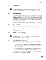
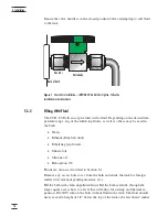
Страница 22: ...ment has not been en ergized for more than 10 days the bath will need to be energized for a dry out period of 1 2 hours before it can be assumed to meet all of the safety requirements of the IEC 1010 1 5 3 Bath Preparation and Filling Caution Before filling the tank with fluid the drain valve must be installed onto the pipe fitting at the back of the bath 5 3 1 Drain Valve Installation Instruction...

Страница 23: ...in Section 8 1 Remove any access hole cover from the bath and check the tank for foreign matter dirt remnant packing material etc Fill the bath with clean unpolluted fluid Fill the bath carefully through the large square access hole to a level that will allow for stirring and thermal ex pansion DO NOT turn on the bath without fluid in the tank The fluid should never exceed a height of 1 2 below th...

Страница 24: ...cess hot fluid if necessary 5 4 Power With the bath power switch off plug the bath into an AC mains outlet of the appropriate voltage frequency and current capacity See Section 3 1 Specifica tions for power details Refer to and read the CAUTION at the front of this manual concerning brownout and over voltage protection 19 5 Installation ...

Страница 25: ...approach The bath generates extreme temperatures Precautions must be taken to prevent personal injury or damage to objects Probes may be extremely hot or cold when removed from the bath Cautiously handle probes to prevent personal in jury Carefully place probes on a heat cold resistant surface or rack until they are at room temperature It is advisable to wipe the probe with a clean soft cloth or p...

Страница 26: ...esigned reflective metal apparatus When calibrating over a wide temperature range better results can generally be achieved by starting at the highest temperature and progressing down to the lowest temperature Probes can be held in place in the bath by using probe clamps or drilling holes in the access cover Other fixtures to hold the probes can be designed The ob ject is to keep the reference prob...

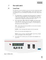
Страница 27: ...tons SET DOWN UP and EXIT are used to set the bath temperature set point access and set other operating parameters and access and set bath calibration parameters A brief description of the functions of the buttons follows SET Used to display the next parameter in a menu and to set parame ters to the displayed value DOWN Used to decrement the displayed value of parameters UP Used to increment the d...

Страница 28: ...derneath the motor cover The stirring motor is mounted on the bath tank lid under the motor cover It drives the stirring propeller to provide mixing of the bath fluid Proper mixing of the fluid is important for good constant temperature stability On the bath lid is a work area access hole This is used for filling the bath with fluids and placement of thermometers and devices into the bath When pos...

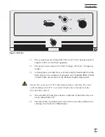
Страница 29: ...e more easily drained at higher temperatures Caution Do not exceed a 100 C fluid temperature for draining The valve could be damaged if 100 C is exceeded Insulate the container from the floor and other objects 4 The serial RS 232 interface attaches to the back of the bath at the con nector labeled RS 232 5 The removable vent panel can be removed to access the condensor for cleaning See Section 12 ...

Страница 30: ...l condensed fluid dripping into the bath from the lid 8 1 2 Viscosity Viscosity is a measure of the thickness of a fluid how easily it can be poured and mixed Viscosity affects the temperature stability of the bath With low vis cosity fluid mixing is better which creates a more uniform temperature throughout the bath This improves the bath response time which allows it to maintain a more constant ...

Страница 31: ...perature sensors it may be important that little or no electrical leakage oc cur through the fluid In such conditions choose a fluid with very high resistivity 8 1 7 Fluid Lifetime Many fluids degrade over time because of evaporation water absorption gel ling or chemical breakdown Often the degradation becomes significant near the upper temperature limit of the fluid substantially reducing the flu...

Страница 32: ...ds Below is a description of some of the more commonly used fluids and their characteristics 8 1 10 1 Water Distilled Water is often used because of its very low cost availability and excellent tem perature control characteristics Water has very low viscosity and good thermal conductivity and heat capacity which makes it among the best fluids for control stability at low temperatures Temperature s...

Страница 33: ... non toxic Silicone oils are fairly expensive 8 1 10 5 Halocarbon 0 8 Halocarbon 0 8 is a low temperature fluid with a wide temperature range It may be used as low as 90 to 100 C before viscosity be comes too great It may be used as high as 70 C before evaporation be comes excessive Halocarbon does not absorb water and will therefore form ice at temperatures below 0 C Ice crystals turn the fluid i...

Страница 34: ...C b NONE 7 0 C 2 50 C 0 7 100 C 1 05 0 8 0 C 0 001 Mineral Oil No 7 5011 10 C v 166 C fl 168 C 15 75 C 5 125 C 0 87 25 C 0 84 75 C 0 81 125 C 0 48 25 C 0 53 75 C 0 57 125 C 0 00025 25 C 0 0007 50 C 5 25 C Silicone Oil Type 200 05 5010 40 C v 130 C fl cc 133 C 5 25 C 0 92 25 C 0 4 0 00028 25 C 0 00105 1000 25 C 10 150 C Silicone Oil Type 200 10 5012 30 C v 209 C fl cc 211 C 10 25 C 3 135 C 0 934 25...

Страница 35: ...ff until the bath temperature reaches the programmed set point When powered on the control panel display will briefly show a four digit number This number indicates the number of times power has been applied to the bath Also briefly displayed is data which indicates the controller hardware configuration This data is used in some cir cumstances for diagnostic purposes 8 4 Heater The power to the ba...

Страница 36: ...ge refrigerant is an HFC known as R 507 The second stage per forms the ultra low cooling Its refrigerant is an HFC R 508B also known as SUVA 95 What this means to you The cascade system is complex and its uncommon nature means that many local refrigeration service technicians may not be able to service it If your bath needs survice call GE Kaye Instruments Customer Service at 1 800 964 KAYE The co...

Страница 37: ...ed in temperature units of degrees Celsius or Fahrenheit The controller is operated and programmed from the front control panel using the four key switches and digital LED display The controller is equipped with a serial RS 232 digital interface for remote operation Operation of the controller using the front control panel is discussed following in Section 9 Operation us ing the digital interfaces...

Страница 38: ...e digital LED display on the front panel allows direct viewing of the actual bath temperature This temperature value is what is normally shown on the dis play The units C or F of the temperature value are displayed at the right For example 10 00C Bath temperature in degrees Celsius The temperature display function may be accessed from any other function by pressing the EXIT button 9 2 Temperature ...

Страница 39: ... Off Scan Rate Display Temperature Configuration Menu Secondary Functions X5 HL LL COOL Adj HL Adj LL Adj COOL Display of Rs EXIT Set Proportional Band Set Cut out Temp R0 Hard Cut out Adj Hard Cut out Adj ALPHA Adj DELTA SET Cal Menu ALPHA Adj R0 DO NOT CHANGE THESE VALUES SEE MANUAL DO NOT CHANGE THESE VALUES SEE MANUAL DELTA BETA Adjust BETA EXIT X5 R0 Hard Cut out Adj Hard Cut out Adj ALPHA Ad...

Страница 40: ... may be adjusted after selecting the set point memory and pressing SET 4 25 0 Set point 4 value in C If the set point value is correct hold EXIT to resume displaying the well temperature Press UP or DOWN to adjust the set point value 28 00 New set point value When the desired set point value is reached press SET to accept the new value and access the temperature scale units selection If EXIT is pr...

Страница 41: ...n function off Press UP or DOWN to toggle the scan on or off Sc On Scan function on Press SET to accept the present setting and continue S Accept scan setting 9 3 2 Scan Rate The next function in the main menu is the scan rate The scan rate can be set from 1 to 99 9 C min The maximum scan rate however is actually limited by the natural heating or cooling rate of the instrument This will be less th...

Страница 42: ...wer will let the user know how stable the bath temperature is The heater power display is accessed in the secondary menu Press SET and EXIT simultaneously and release The heater power will be displayed as a percentage of full power 10 00C Bath temperature S E Access heater power in secondary menu SEC Flashes 12 0 P Heater power in percent To exit out of the secondary menu hold EXIT To continue on ...

Страница 43: ...ates The proportional band width is set at the factory to a value between 0 5 and 1 0 C The proportional band width may be altered by the user if he desires to optimize the control characteristics for a particular application The proportional band width is easily adjusted from the front panel The width may be set to discrete values in degrees C or F depending on the selected units The proportional...

Страница 44: ...ols until it reaches a few degrees below the cutout set point temperature At this point the cutout resets and al lows normal operation The cutout set point may be accessed within the secondary menu Press SET and EXIT to enter the secondary menu and show the heater power Then press SET twice to access the cutout set point S E Access heater power in secondary menu 12 0 P Heater power in percent S Ac...

Страница 45: ...ng parameters menu contains the High Limit Stir Speed and Cool ing parameters 9 9 1 High Limit The High Limit Parameter adjusts the upper set point temperature The factory default and maximum temperature are set to 100 C For safety a user can ad just the High Limit down so the maximum temperature set point is restricted HL High Limit parameter Press SET to enable adjustment of HL HL Flashes HL and...

Страница 46: ...han about 35 C As a result cooling is ON only if the cooling func tion is ON the cooling switch is ON and both the bath temperature and the set point are less than about 35 C The cooling function is indicated by CooL Flashes CooL and then displays the setting CooL OFF Current cooling setting The setting may be changed using UP or DOWN and pressing SET CooL On New cooling setting 9 10 Serial Interf...

Страница 47: ...sure ments transmitted from the serial interface If the sample rate is set to 5 the in strument transmits the current measurement over the serial interface approximately every five seconds The automatic sampling is disabled with a sample period of 0 The sample period is indicated by SPer Flashes SPEr and then displays the setting SP 1 Current sample period seconds Adjust the value with UP or DOWN ...

Страница 48: ...er has access to the Hard Cutout and a number of the bath calibration constants namely R0 ALPHA DELTA and BETA These values are set at the factory and should not be altered The cor rect values are important to the accuracy and proper and safe operation of the bath Access to these parameters is available to the user only so that in the event that the controller memory fails the user may restore the...

Страница 49: ...d is user settable 9 11 2 R0 This probe parameter refers to the resistance of the control probe at 0 C The value of this parameter is set at the factory for best instrument accuracy 9 11 3 ALPHA This probe parameter refers to the average sensitivity of the probe between 0 and 100 C The value of this parameter is set at the factory for best instrument accuracy 9 11 4 DELTA This probe parameter char...

Страница 50: ...onitor the temperature and access any of the other controller functions all using remote communications equipment Communications commands are summarized in Table 3 on page 50 10 1 Serial Communications The bath is installed with an RS 232 serial interface that allows serial digital communications over fairly long distances With the serial interface the user may access any of the functions paramete...

Страница 51: ...ally press SET to enter the serial parameter menu In the serial interface parame ters menu are the baud rate the sample rate the duplex mode and the linefeed parameter 10 1 2 1 Baud Rate The baud rate is the first parameter in the menu The display prompts with the baud rate parameter by showing bAUd Press SET to choose to set the baud rate The current baud rate value is displayed The baud rate of ...

Страница 52: ...bles OFF transmission of a linefeed charac ter LF ASCII 10 after transmission of any carriage return The default setting is linefeed off The mode may be changed using UP or DOWN and press ing SET 10 1 3 Serial Operation Once the cable has been attached and the interface set up properly the control ler will immediately begin transmitting temperature readings at the pro grammed rate The serial commu...

Страница 53: ...1 to 99 9 Secondary Menu Read proportional band setting pr opband pr pb 999 9 pb 15 9 Set proportional band to n pr opband n pr 8 83 Depends on Configuration Read cut out setting cu tout cu cu 9999 C or F cu 105 C in Set cut out setting to n degrees cu tout n cu 95 25 to 115 C Read heater power duty cycle po wer po po 999 9 po 1 0 Configuration Menu Read high limit hl hl hl 999 hl 126 Set high lim...

Страница 54: ...of f lf of Read R0 calibration parameter r 0 r r0 999 999 r0 100 578 Set R0 calibration parameter to n r 0 n r 100 324 90 to 110 Read ALPHA calibration parameter al pha al al 9 9999999 al 0 0038573 Set ALPHA calibration parameter to n al pha n al 0 0038433 002 to 005 Read DELTA calibration parameter de lta de de 9 99999 de 1 507 Set DELTA calibration parameter de lta n de 1 3742 0 3 0 Read BETA ca...

Страница 55: ...e limits The stated accuracy of the instrument can be found in the specification table in Section 3 1 Because of the way the calibration parameters affect the temperature the simplest way to proceed is to measure the errors at 0 C 100 C 50 C and 70 C and adjust R0 ALPHA DELTA and BETA at each point re spectively Be aware that you must use the appropriate fluid at each tempera ture Follow these ste...

Страница 56: ...For example if the bath temperature is high by 0 1 C at 50 C then de crease DELTA by 0 4 Set the set point to 70 C and allow adequate time for the bath to reach this temperature and stabilize Adjust the BETA calibration parameter see Section 9 11 5 to make the bath temperature as measured with the standard thermometer match the set point The approximate ratio between a change in BETA and a change ...

Страница 57: ...h for the first year and regularly thereafter This fluid check provides a baseline for knowledge of bath operation with clean usable fluid Once some fluids have become compromised the break down can occur rapidly Particular attention should be paid to the viscosity of the fluid A significant change in the viscosity can indicate that the fluid is contaminated being used out side of its temperature ...

Страница 58: ...lation is visible remove the rear panel to clean out the dust or dirt Use a vacuum with a brush to remove the dirt Do not use compressed air as it might drive the dirt be tween the fins where it may become lodged preventing airflow If the instrument is used in a manner not in accordance with the equip ment design the operation of the bath may be impaired or safety hazards may arise 56 12 Maintenan...

Страница 59: ...Rate set low If the display flashes any of the following err 1 This error means there is a RAM error err 2 This error means there is a NVRAM error err 3 This error means there is a RAM error err 4 This error means there is an ADC set up error err 5 This error means there is an ADC ready error err 6 This error means there is a SENSOR error err 7 This error means there is a HtrCTL error Cycle the po...

Страница 60: ...C Voltage Cutout 12 5 203 257 VAC Voltage Cut In 7 5 213 247 VAC See the Caution in the front of this manual for additional information 13 2 CE Comments 13 2 1 EMC Directive This instrument has been tested to meet the European Electromagnetic Compat ibility Directive EMC Directive 89 336 EEC The Declaration of Confor mity for your instrument lists the specific standards to which the unit was teste...

Страница 61: ...ts to be grounded T1 LTR DESCRIPTION BY APPROVAL DATE REVISIONS Blue 16 Brown 16 Vio 18 Vio 18 K2 Solid State Relay For 230 VAC 10 Amps 250 V Slow Blow For 115 VAC 6 Amps 250 V FB For 115 VAC 20 Amps 250 V Slow Blow Vio 22 Gry 22 Blk 22 Grn Yel 14 Grn Yel 14 STIR MOTOR COOLING J4 J1 J3 J1 J6 3 2 W4 W5 W6 W7 W8 W9 W13 W14 W15 W16 W19 W20 W26 W27 W23 W24 W25 W31 W32 W33 W34 W35 W36 W37 W18 W17 W40 W...

Отзывы: