background image

Installation Instructions

20

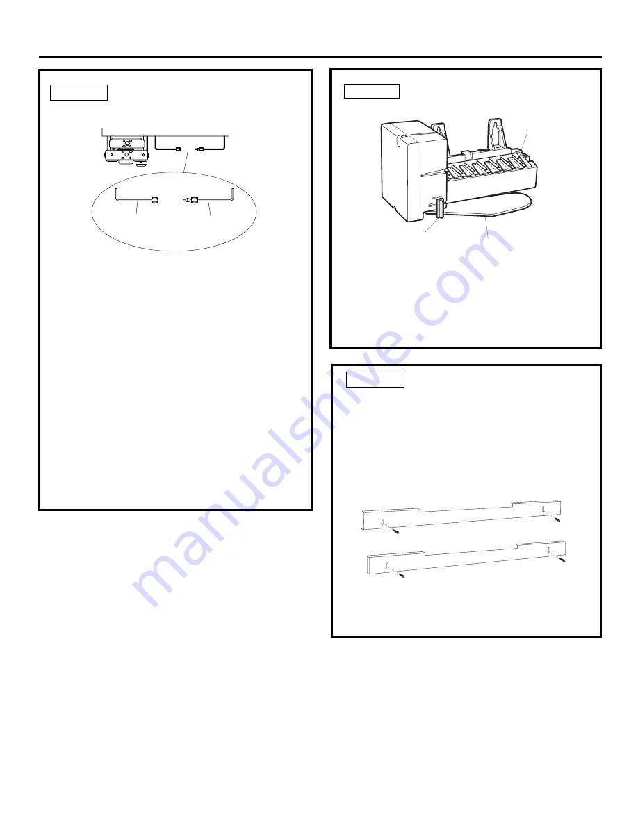
STEP 10  CONNECT WATER SUPPLY

(FREEZER MODELS ONLY)

• Locate and bring the tubing to the front 

of the cabinet.

• Turn the water on to flush debris from the line. 

Run about a quart of water through the tubing 
into a bucket, then shut off the water.

Copper Tubing:

• Slip a 1/4" nut and ferrule (provided) over both ends 

of the copper tubing. Insert the tube into the union 
fitting on the unit and tighten the nut to the union.

• Turn on the water to check for leaks.

GE SmartConnect

Tubing:

• Insert the molded end of the tubing into 

the refrigerator or freezer connection. Tighten 
the compression nut until it is just hand-tight.

• Tighten one additional turn with a wrench.

Overtightening can cause leaks!

• Turn on the water to check for leaks.

NOTE:

Make sure excess tubing length does not 

interfere with the toekick installation.

Freezer

Water Supply

House

Water Supply

STEP 12  INSTALL TOEKICK

• Locate the supplied toekick (shipped taped to the side

of the product). Install with 2 screws provided, adjust
to the desired height and tighten the screws.

• A custom toekick can be installed to match 

or complement the surrounding cabinetry. 
Use the supplied toekick as a template to cut 
out the notch.

IMPORTANT:

The vented toekick must remain 

unobstructed for proper air circulation and 
operation.

Supplied Toekick

1/4" or Thicker Toekick

STEP 11  START ICEMAKER

• Slide the switch to ON. The icemaker will begin opera-

tion automatically.

• Be sure nothing interferes with the sweep 

of the feeler arm. 

• Discard the first full bucket of ice cubes.
• To turn the icemaker off, slide the switch to OFF.

Icemaker

Feeler Arm

Power
Switch

Содержание Built-In All-Refrigerator/Free

Страница 1: ...Installation Instructions 31 46148 224D2601P001 06 08 JR 36 Built In All Refrigerators and All Freezers monogram com ...

Страница 2: ... these instructions completely and carefully IMPORTANT Save these instructions for local inspector s use Observe all governing codes and ordinances Note to Installer Be sure to leave these instructions with the Consumer Note to Consumer Keep these instructions with your Owner s Manual for future reference WARNING This appliance must be properly grounded See Grounding the Unit page 10 AVERTISSEMENT...

Страница 3: ... copper tubing or GE QuickConnect kit between the cold water line and water connection location long enough to extend to the front of the unit Installation of an easily accessible shut off valve in the water line is required DIMENSIONS AND CLEARANCES Shipping height The product can be adjusted to fit into a cutout that is 83 1 2 min to 84 1 2 max height Note that the top case trim at the front is ...

Страница 4: ...y is recommended for each product Clearances for Multiple Single Door Installations In a side by side installation of a left and right door swing product a 1 clearance between the units is required Order ZUGSS2 Stainless Steel Unified Grille Panel Kit or ZUG2 Custom Panel Unified Grille Panel Kit for one continuous grille panel Clearances for two products installed side by side with the same left ...

Страница 5: ...factory setting Scale 1 1 Frameless Cabinets The case trim overlaps cabinets at the top and sides Therefore frameless cabinets may require filler strips to prevent interference with cabinet door swing The opening must allow for filler strips ...

Страница 6: ... Nominal Size Case Trim Refrigerator or Freezer Door Top View 90 DOOR SWING optional setting Scale 1 1 Frameless Cabinets The case trim overlaps cabinets at the top and sides Therefore frameless cabinets may require filler strips to prevent interference with cabinet door swing The opening must allow for filler strips ...

Страница 7: ...pplied handles shown in 1 4 panel position Door Handle The standard supplied handles can be adjusted to accommodate both framed or overlay panels Custom handles of your choice supplied by your cabinet maker can also be installed on overlay panels If desired you may order ZKHSS2 Monogram stainless steel tubular handle kit for 3 4 overlay panels This kit contains 2 handles Only 1 kit is needed if in...

Страница 8: ...nd backer panel IMPORTANT NOTE Maximum total weight for assembled door panel is 67 pounds Maximum total weight for assembled grille panel is 11 pounds Assemble the panels with glue and screws Center the spacer panel on the backer panel left to right and top to bottom Secure the panels with glue Center the spacer and backer panel on the overlay panel and secure with glue and screws Screws must be c...

Страница 9: ...er keys in the front side trim ZUG2 GRILLE PANEL DIMENSIONS The ZUG2 unified grille panel kit provides for the installation of a framed or overlay grille panel Depending on installation height Assemble the overlay panels in the same manner as the door panel Framed Panel Dimensions A Width B Height 1 4 Framed Panel 69 7 8 8 7 8 Overlay Panel Dimensions A Width B Height 1 4 Backer Panel 69 7 8 8 7 8...

Страница 10: ...roperly grounded Where a standard 2 prong wall outlet is encountered it is your personal responsibility and obligation to have it replaced with a properly grounded 3 prong wall outlet 4 Washers 2 Hair Pin Cotters 3 lag screws 5 toggles with bolts Water filter bypass plug Supplied Toekick Toekick Secured to side of unit Anti Tip bracket Secured to side of unit MATERIALS REQUIRED 1 4 copper water li...

Страница 11: ...ause the line is under pressure at all times Other types of plastic may crack or rupture with age and cause water damage to your home GE SmartConnect Refrigerator Tubing Kits are available in the following lengths 2 6 m WX08X10002 6 1 8 m WX08X10006 15 4 6 m WX08X10015 25 7 6 m WX08X10025 The unit is secured to the skid with 4 slotted tie down straps Remove the four 5 16 bolts from the base channe...

Страница 12: ...he wall Using a level draw a horizontal line on the wall at this height Locate at least 2 studs on the back wall Mark these points on the horizontal line Place the bottom of the wall bracket with tabs on the horizontal line Align the center notch on the bracket with the center line on the wall The anti tip wall bracket has a series of holes Select 2 holes that match with the located studs Make sur...

Страница 13: ...3 Wall toggles are installed in the drywall and metal studs for stability Install the wall toggles as follows Drill 1 2 holes at the wall markings made in the holes at the ends of the wall bracket Hold the metal channel flat against the plastic straps and slide the channel through the hole Gently pull back at the ends of the plastic straps to make the channel rest flush behind the wall Hold the en...

Страница 14: ...d easily Gently pull forward on the left side of the grille to open for access This grille will not be completely removed Power Cord Locate the power cord inside the left cavity If it has not been adjusted so the plug is easily accessible do so now L Bolt Left Grille Open Power Cord Location L Bolt Left Grille Open Power Cord Location Move Unit into Final Position Move refrigerator toward its fina...

Страница 15: ...1 If the installation requires more than 84 1 2 height the installer should elevate the unit on a sheet of plywood or runners Cabinetry trim could also be added across the top of the opening to shorten the opening If you attempt to raise the unit more than 1 you will damage the front leveling legs and the rear leveling wheels PRUDENCE Les roues de nivellement arrière et les pattes de nivellement a...

Страница 16: ...e on the rod that is closest to the unit A hair pin cotter will be put through this hole to secure the rod If this hole appears to be too far away for a snug fit against the unit add the washers one at a time until the pin will fit tightly into the hole Align the straight section of the pin with the hole from the underside of the rod Push the pin up until it snaps into position Pliers may be used ...

Страница 17: ...oor stop pin locations The pin is factory installed in the 130 position Close the door From below use pliers to unscrew the door stop and reinstall into the 90 position Loosen the screws on the side trim behind the frame Remove the bottom trim Slide the panel over the metal baker panel and into the trim If necessary tap with a wood block until the panel slips under the top trim piece Reassemble th...

Страница 18: ... Secure Handle Use Front Holes to Secure Trim Right hand models shown Use the same instructions for left hand models IF YOU ARE INSTALLING OVERLAY PANELS GO TO STEP 10A Install Door Panel Open the door to 90 Remove the 6 Phillips head screws from the door handle Remove the handle Retain all screws Remove the 6 screws holding the trim lift off the trim Retain the screws Slide the framed panel into ...

Страница 19: ... handle and hardware Secure the door trim using new handle side trim Discard the supplied handle Right hand models shown Use the same instructions for left hand models Install Door Panel Open the door to 90 Remove the 6 Phillips head screws from the door handle Remove the handle Retain all screws Remove the 6 screws holding the trim lift off the trim Retain the screws Slide the overlay panel into ...

Страница 20: ...leaks Turn on the water to check for leaks NOTE Make sure excess tubing length does not interfere with the toekick installation Freezer Water Supply House Water Supply STEP 12 INSTALL TOEKICK Locate the supplied toekick shipped taped to the side of the product Install with 2 screws provided adjust to the desired height and tighten the screws A custom toekick can be installed to match or complement...

Страница 21: ...21 Notes ...

Страница 22: ...22 Notes ...

Страница 23: ...23 Notes ...

Страница 24: ...orming installations described in this book safety glasses or goggles should be worn For Monogram local service in your area call 1 800 444 1845 NOTE Product improvement is a continuing endeavor at General Electric Therefore materials appearance and specifications are subject to change without notice 31 46148 224D2601P001 06 08 JR ...

Отзывы: