


7 | GE Oil & Gas
© 2014 General Electric Company. All rights reserved.
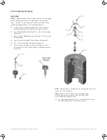
3� Remove the positioner from the bracket� The tubing and
fittings on each side of the positioner must be taken off and
installed in the opposite corner from their original position
(see piping schematic provided by GE), then reattach to
the positioner� This will allow the positioner to maintain the
actuator failure mode when the positioner is turned upside
down�
4� Move the bracket assembly, tube assembly, and cover plate
to the positions shown on the desired drawing�
5� Install the positioner in the opposite direction of its original
position (upside down if it was right side up, right side up if it
was upside down)�
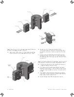
6� Using parts from the factory kit, assemble the spring and sur-
rounding hardware according to the drawing of the desired
configuration� (Note: All original parts may not be used when
converting from close on increasing to open on increasing�)
7� The entire bracket assembly or the outer angle may need
to be turned upside down to accommodate the new spring
height�
8� Reconnect the supply, instrument, and output lines according
to piping schematic supplied�
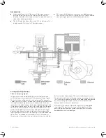
NOTE: The flow direction must be maintained through the
positioner bodies when re-piping� (i�e�, the flow [supply or
exhaust] moves from P1 to P2 and P3 to P4)�
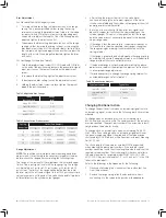
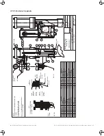
Table 4. Extension Rods for Positioners to Close on
Increasing Signal
Conversion to Split Range
Converting a standard positioner to a split range positioner (pneu-
matic input other than 3-15 psi or 6-30 psi), requires ordering the
proper conversion kit from the factory� This kit will include a bias
spring and bias spring cartridge� If required, it will also contain a
new range spring and mounting spacers�
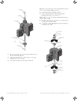
1� For close on increasing positioner: Remove the cap on the top
of the positioner along with the spring inside it�
For open on increasing positioner: Remove the mounting
bracket holding the cap on the bottom of the positioner� Then
remove this cap along with the spring inside it�
2� Replace the cap and spring with the larger bias spring
cartridge and bias spring found in the kit� Make sure the bias
adjustment screw in the bias spring cartridge is snug against
the bias spring and the spring is centered before tightening
the spring cartridge�
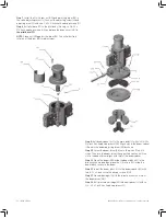
3� For open on increasing positioner: Remove the washer and
jam nut from the adjusting screw in the bias spring cartridge�
Reattach the mounting bracket upside down from its original
position�
4� Slide the thread spacer (brass bushing) over the adjusting
screw and tighten the washer and jam nut against the thread
spacer�
5� If a range spring was sent with the kit, remove the existing
range spring and replace it with the new one�
6� Adjust the unit per the Adjustment Procedures�
Stroke
With Transmitter
Without Transmitter
4”
25-1402
25-8001
6”
25-8136
25-1093
8”
25-1402
25-1423
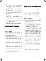
NOTE: Refer to Table 1 and Table 2 for bias and range spring part
numbers
Table 5. Split Range Conversion Kits
Maintenance and Inspection
As with all precision equipment, it is necessary to periodically test
the positioner to help ensure top performance� We recommend
the following procedure once a year�
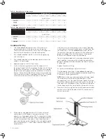
1� Shut off supply pressure and bleed down at positioner� Note
the settings of the variable orifices and remove them from
the orifice assembly� Clean them thoroughly and reinstall
using new o-rings, while being sure to install each orifice in
the same hole from which it was removed (the orifice and
block have matching numbers for this purpose)� Reset orifices
to original settings� Turn on supply pressure�
2� Apply a midrange signal to the positioner� Allow the control
valve to become stationary at about 50 percent of the range�
Close the cylinder block valves or move the MCV-3 handle
to the manual position� The positioner is now isolated from
the cylinder� Apply a ± 1/4 psig signal change� Observe the
response in the output gauges� The output pressure should
develop differential pressure equal to 20 percent of the power
gas pressure� If the output pressure does not show immedi-
ate response, the positioner may have too much deadband�
Reduce the deadband by turning the drum in the direction
of decreasing numbers� If the pressures do not respond in
the correct direction when reversing the instrument signal
change, the unit has internal friction� Disassemble the unit
and replace all rubber goods�
3� Check the integrity of the balance valve seats by increasing
the deadband by one full number� When the cylinder top and
bottom gauges are equal to the power gas, the exhaust port
should not exhibit any bleed gas� If either of these tests fail,
then the positioner is not properly adjusted or the unit needs
to be reassembled with new rubber goods�
4� Soap test around all diaphragm interfaces, orifice
assemblies, and vents� If any leaks are found around the
diaphragms, refer to the assembly instructions for replace-
ment of all internal rubber parts�
5� Observe the operation of the gauges� If any gauges are
defective, replace them�
6� Check range and bias� If necessary, readjust per Adjustment
Procedures� Should problems arise or more information is
required, call toll free
(800) 323-8844
for assistance�
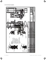
Stroke
Close on
Increasing
Open on
Increasing
Reference
Drawings
4 inch
25-6014
25-1464
Proportional:
35-0513
35-0313/A
35-0511
35-0511/A
6 inch
25-6014
25-1465
Proportional:
35-0522
35-0529
8 inch
26-6014
25-1466
Tailrod:
Содержание Becker HPP-5
Страница 18: ... ...


