background image

Becker HPP-5 High Pressure Positioner Maintenance and Operation Manual  |  2

© 2014 General Electric Company. All rights reserved.

Technical Assistance

Should you have any questions, you may contact your local GE 

representative�

Applications

n  

Primary Pressure Control

n

  Overpressure Protection (Monitor)

n  

Underpressure Protection (Standby)

n  

Relief Valve

n  

Backpressure Control

Power Plant Type Applications*

n  

When unique “Bleed to Pressure System” BPS™ feature can  

be used

n  

Any large downstream systems (city gate stations, inter-

system pressure limiting)

n  

Suction control to reciprocating compressors* 

n  

Double-stage cut (working monitor regulator*)

* (consult Becker for additional information)

Guidelines for Usage

Large Volume Control Valve Actuators: Control valves that require 

large volume actuators may require Model VB-250 volume 

boosters to ensure adequate stroking speed� HPP-5 positioners 

are NOT compatible with volume boosters� The HPP-4 positioner 

must be used�

Bleed to Pressure System (BPS): The HPP-5 positioner is typically 

used for applications where no discharge pressure of less than 

350 psig is available� The very low steady state bleed of the 

positioner makes it efficient for reducing atmospheric emissions� 

The HPP-5 positioner is also compatible with the Becker BPS�

High Gain Systems: The HPP-5 positioner is not preferred for this 

application� It may be successfully used with small diameter (4 

inch and smaller) ball valves for this application, but its limited 

orifice capacity makes it too slow for controlling larger valves�

CVE Globe Pattern Control Valves: The Becker HPP series position-

ers are compatible with globe style control valves, but require a 

minimum of 2 inches of actuator stroke for proper feedback and 

operation�

This makes it impossible to use this positioner with most globe 

valves smaller than 4 inch port size�

Compatible Actuators:


n


Becker RPDA Actuators (Rotary Piston Double-Acting)


n


Becker LPDA Actuators (Linear Piston Double-Acting)


n


Other manufacturer’s double-acting piston actuators*

*Consult GE for additional information

Retrofit Compatibility:

Excellent performance is achieved by pairing the HPP-5 positioner 

with genuine GE control valve actuators� Should you already 

have existing control valve actuator(s) in service, the addition of a 

Model HPP-5 positioner can improve performance and eliminate 

atmospheric bleed emissions if using the BPS (Bleed to Pressure 

System) feature�

Some Compatible Actuators:


Bettis T-Series piston actuators


n  

Fisher Type 470 piston actuators


Fisher Type 1061 piston

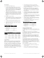
Technical Specifications

Input Signal           Standard: 
                              Adjustable:

3-15 pis or 6-30 psi 
Zero is adjustable from 
2-30 psig, span is adjustable 
from 5-24

Output Signal

Pneumatic pressure as required 
by the actuator up to full supply 
pressure

Loss of Signal     Direct Acting: 
                         Reverse Acting:

Open on loss of signal 
Close on loss of signal

Connections

All Ports: 1/4 inch N�P�T�

Actions               Direct Acting: 
                         Reverse Acting:

Field-reversible 
Field-reversible

Performance

Resolution: 1%* 
Hysteresis: 0�5%*

Flow Capacity

CV = �1

Steady State Gas Consump-
tion

Near zero flow capacity

Power Gas Requirement 
       
Discharge to Atmosphere:

Dry, filtered (100 micron) gas 
150 psig maximum

Operative Temperature 
Limits

-20°F to 160°F 
(-28°C to 70°C)

Housing

Meets NEMA3 classification 
(weather tight)

Installation Orientation

Vertical or horizontal position 
allowable

Approximate Weight

15 pounds

*Resolution and repeatability figures reflect a positioner that is adjusted with a 

minimum deadband to reduce bleed gas� If the deadband is eliminated (slightly 

increasing the bleed gas), resolution and repeatability will improve�

Materials of Construction

External Parts

Anodized 2024 Aluminum/316 SS Available

Internal Parts

316 SS and Anodized 2024 Aluminum

Feedback Lever

316 Stainless Steel

Range Spring

Plated Music Wire

Diaphragms

Buna-N with Nylon Reinforcement

Seats and O-rings

Buna-N

Tubing

316 Stainless Steel

Fittings

316 Stainless Steel

Guages

2-1/2 inch Dial Liquid Fi lled Brass Connection 
with Stainless Steel Case (Stainless Steel 
Connection Option)

Maximum Supply Regulator Capacity

Q = 312�86 x P1 x CV x

 1

G x (T + 460)

Q = Min� Supply Regulators Capacity (scfh)

G = Specific Gravity of Gas

T = Operative Temperature (°F)

CV = Flow Factor

P1 = Supply Pressure to Positioner (psig)

Содержание Becker HPP-5

Страница 1: ...GE Oil Gas GE Data Classification Public HPP 5 High Pressure Positioner Installation and Maintenance Manual ...

Страница 2: ...ower pressure downstream or fuel gas system eliminating bleed gas completely This means significant savings because it limits expensive bleed gas and decreases the environmental impact of atmospheric hydrocar bons on diminishing natural resources Description The Becker HPP 5 positioner is used in control valve assemblies with a controller or I P transducer and double acting actuator to provide acc...

Страница 3: ...t GE for additional information Retrofit Compatibility Excellent performance is achieved by pairing the HPP 5 positioner with genuine GE control valve actuators Should you already have existing control valve actuator s in service the addition of a Model HPP 5 positioner can improve performance and eliminate atmospheric bleed emissions if using the BPS Bleed to Pressure System feature Some Compatib...

Страница 4: ...the supply and discharge pressures In steady state the forces imposed on the balance beam by the input signal diaphragm and the range spring are equal therefore the top and bottom balance valves in the positioner are at or near their closed positions The cylinder top and bottom pressures are both equal to power gas pressure and the control valve is stationary An increase in the input signal pressu...

Страница 5: ...greater accuracy from a smaller deadband and minimal bleed gas Your HPP 5 positioner will come factory adjusted for your particular application The use of the adjustment procedures will be necessary upon installation of a rubber goods replacement kit or any other disassembly or reassembly of the positioner Adjustment Procedure The sensitivity adjustment drum on one end of the positioner determines...

Страница 6: ...ual position If the actuator is not equipped with an MCV 3 manual control valve use the block valve 1 4 inch ball valve installed between the positioner output and the actuator Once the actuator has reached its desired position based on the mid signal applied to the instrument port Step 5 place the block valve in the closed position 7 Final Sensitivity Drum Adjustment for positioner s bleeding to ...

Страница 7: ... the start of the valve travel continue increasing the instrument signal until the valve stroke is completed and the cylinder output gauges show full power gas pressure differential 2 Be sure not to overshoot at this point as any signal level above this upper limit will show the same reading on the cylinder gauges This point is the highest end of the range and the value may not necessarily be equa...

Страница 8: ...ge spring was sent with the kit remove the existing range spring and replace it with the new one 6 Adjust the unit per the Adjustment Procedures Stroke With Transmitter Without Transmitter 4 25 1402 25 8001 6 25 8136 25 1093 8 25 1402 25 1423 NOTE Refer to Table 1 and Table 2 for bias and range spring part numbers Table 5 Split Range Conversion Kits Maintenance and Inspection As with all precision...

Страница 9: ...des adequate preventative maintenance Parts Ordering The following is provided to allow the ordering of replacement parts Please specify the Becker instrument serial number when ordering parts this can be found on the stainless steel tab attached to the pilot by the 7 16 hex head cap screws If the instrument was supplied as a complete valve regulator package the stainless tag attached to the actua...

Страница 10: ...ORIFICE ASSY 7 1 35 1519 SEAT COVER 8 1 98 3056 1 2 20 JAM NUT SS 9 1 25 1124 BEAM ADJUSTING DRUM 10 1 25 1213 DIAPHRAGM 11 6 95 2609 O RING 010 12 1 25 1065 1 2 20 SPECIAL NUT ALUM 13 1 98 2950 1 8 ROLL PIN SS 14 4 98 3144 8 32 x 1 SHCS 15 1 25 1086 BEAM BLOCK 16 1 35 1506 OUTSIDE PISTON 17 4 98 3089 3 16 x 1 2 ROLL PIN SS 18 4 98 3180 1 4 20 x 2 1 2 HHCS 19 1 35 1013 GAUGE MANIFOLD 20 6 95 2615 ...

Страница 11: ...E ON INCREASING SIGNAL 21 ROD CLEVIS HOUSING ASSY INSTRUMENT GAUGE HPP 09 13 93 NTS TS DRAWING NUMBER APPR0VED BY B DWG SIZE REVISED BY DB REVISED DATE 2 12 04 DRAWN BY DATE SCALE 30 1208 ITEM QTY PART DESCRIPTION 1 1 95 2643 O RING 24 2 1 25 1095 SPRING RETAINER 3 1 95 2644 O RING 30 4 1 25 1289 SHORT TUBING 5 1 TUBE HOLDER 6 1 25 1310 ACCESS COVER 7 1 25 1131 BOTTOM COVER 8 1 25 1230 8 STK HPP 2...

Страница 12: ... POSITION 2 THE ORIFICE ASSEMBLY IS CALIBRATED TO ASSURE EQUAL RATE OF FLOW FROM BOTH ORIFICES 1 REGULATOR TO CLOSE ON INCREASING SIGNAL N0TES HPP INSTRUMENT GAUGE BECKER Precision Equipment DRESSER INC ITEM QTY PART DESCRIPTION 1 1 50 1230 FLANGE 2 1 25 1310 ACESS COVER 3 1 98 3171 8 32 X 1 4 RHMS 4 1 25 1149 RANGE SPRING LOCK 5 1 RANGE SPRING 6 1 95 2643 O RING 024 7 1 25 1134 LONG TUBING 8 1 95...

Страница 13: ...b Insert the balanced valve assembly C with the stem facing downward 1c Insert the second balanced valve assembly C with the stem facing upward 1d Insert the second strainer D1 and spacer D assembly 1e Insert the top seat rubber facing downward E 1f Secure the seat assembly to the pilot body block F with two washers C1 seat cover B and two flat head machine screws A NOTE Install washers to compens...

Страница 14: ...h four 1 4 20 x 2 1 2 inch stainless steel hex head cap screws J by lining it up with roll pins M in pilot body block F Step 4 Test the pilot body block F for leakage Using 1 4 inch NPT plugs plug the orifice block ports K and the gauge manifold N 4a Connect a pressure source to the orifice block K as shown Use approximately 100 psig for testing 4b With the pressure source activated soap test arou...

Страница 15: ...ly with two 8 32 x 1 inch SHCS T Step 6 Slide 012 O ring CC onto the outside piston I and into the groove near its base 6a Install one washer Z onto the shaft of the outside piston I with the grooves facing upward 6b Install the convoluted diaphragm AA onto the shaft of the outside piston as shown 6c Install one washer Z onto the shaft of the outside piston with the grooves facing downward 6d Tigh...

Страница 16: ...ith six 1 4 20 x 3 4 inch hex head cap screws DD Align holes in the beam spacer JJ and in the beam adjusting drum KK as shown Step 10 Screw the beam drum KK on to the piston F until it stops Then turn the beam drum the opposite direction until the slot in the beam drum aligns with that of the beam spacer Step 11 Place the beam NN inside the beam block LL in the direction shown and then place the 1...

Страница 17: ...Becker HPP 5 High Pressure Positioner Maintenance and Operation Manual 16 2014 General Electric Company All rights reserved ...

Страница 18: ... ...

Отзывы:

Похожие инструкции для Becker HPP-5