


K0582 Revision B
May 2015
3
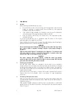
Figure 2 Pressure connection
Torque tighten the sensor in accordance with the system installation manual.
Electrical connections
2.4
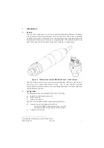
The DPS 5000 series sensors employ a 4 wire I
2
C-bus user electrical interface:
Supply
+
Serial
data
(SDA)
Serial
clock
(SCL)
Supply –
The sensor may be used standalone or as part of a network of compatible I
2
C-bus
devices.
CAUTION
The DPS 5000 is intended for use within networks operated from a single supply
at a voltage within the range 2.7 V to 3.6 V. Operation outside these limits is not
guaranteed and may damage the sensor.
The sensor interface includes 2 reserved signals. These should be left open circuit
as connecting to these signals may result in incorrect sensor operation.
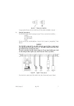
Figure 3
Typical I
2
C-bus network
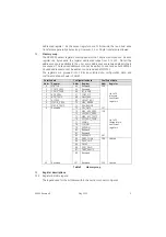
The electrical connections to the sensors are colour coded as shown in Table 1.


