background image

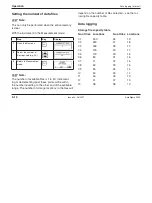
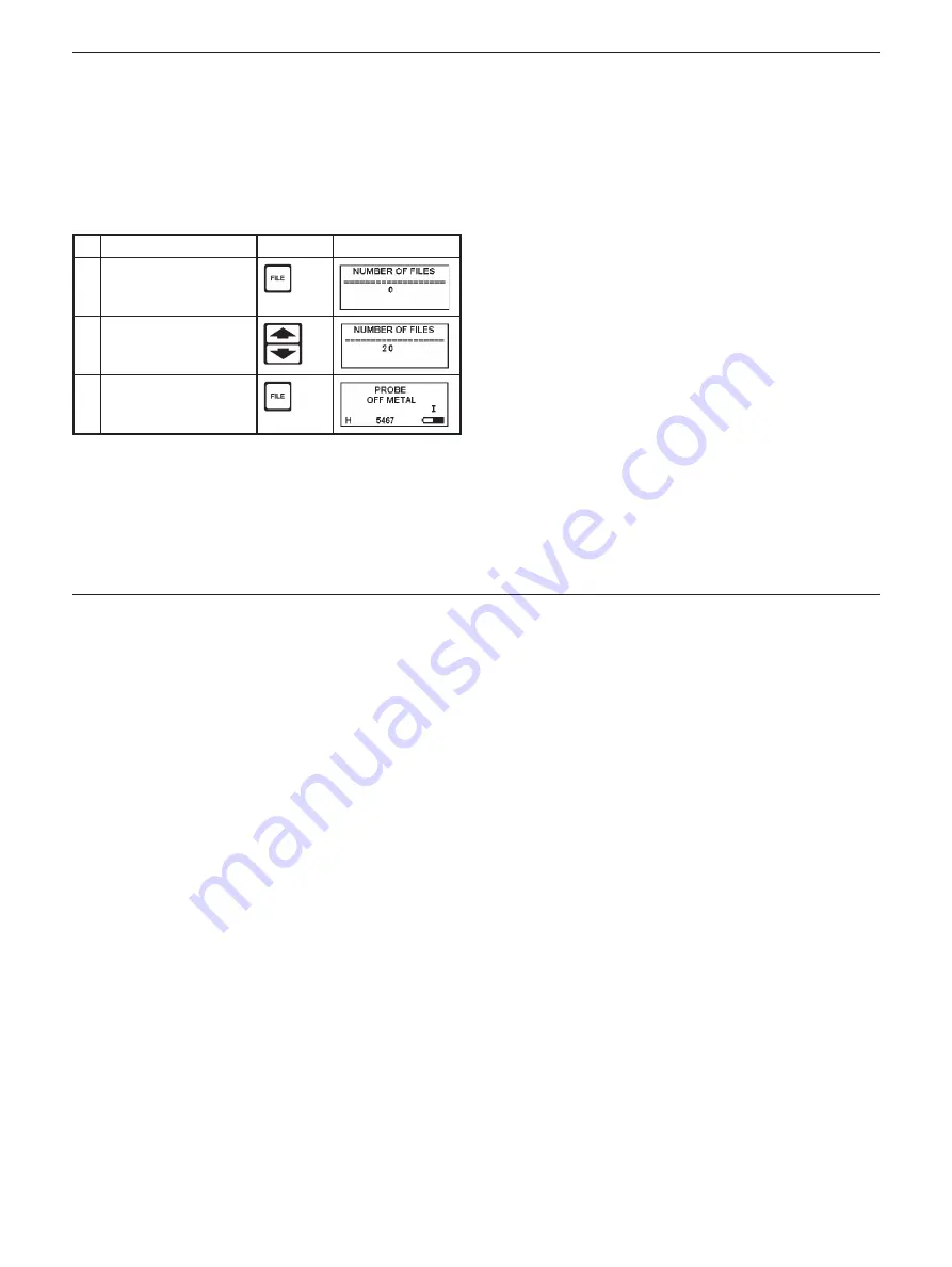
 Setting the number of data fi les

Note:

This can only be performed when the entire memory 
is clear.

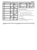
With the instrument in the Measurement mode:

Step

Key

Display

1

Open the fi le menu.

2

Select the number of 
fi les required (e.g. 20).

3

Return to Measurement 
mode.

Note:

The number of available fi les is 1 to 50. Increment-
ing or decrementing past these points will result in 
the number reverting to the other end of the available 
range. The number of storage locations in the fi les will 

depend on the number of fi les selected – see the fol-
lowing fi le capacity table.

 Data logging

 Storage fi le capacity table

No of fi les  Locations 

No of fi les  Locations

01 500 

26 19

02 250 

27 18

03 166 

28 17

04 125 

29 17

05 100 

30 16

06 83 

31 16

07 71 

32 15

08 62 

33 15

09 55 

34 14

10 50 

35 14

11 45 

36 13

12 41 

37 13

13 38 

38 13

Data logging (internal)

Operation

5 - 10


Issue 04, 06/2007 

AutoSigma 3000

Содержание AutoSigma 3000 DL

Страница 1: ...AutoSigma 3000 Technical Reference and Operation Manual Ident No 071 002 022 47DH01 105 952...

Страница 2: ...This Issue 04 06 2007 applies to the software version 1 0 Subject to change without notice Rev 02...

Страница 3: ...3 1 Battery installation 3 2 Power requirements 3 2 3 2 Probe connection 3 3 3 3 Probe identification 3 4 3 4 Entering probe code data 3 5 3 5 General parameter setting 3 6 3 6 Start up 3 7 Normal swi...

Страница 4: ...ging in a reading general 5 11 Selecting a file for logging 5 12 Clearing a file 5 13 Accessing a file location containing stored data 5 13 5 8 Customising the operating mode 5 14 Storing a customised...

Страница 5: ...8 1 Cleaning 8 2 8 2 Care of Batteries 8 2 9 Appendix 9 1 9 1 EC Declaration of Conformity 9 2 9 2 Manufacturer Service address 9 2 Great Britain 9 3 USA 9 3 Germany 9 3 10 Index 10 1 Content AutoSigm...

Страница 6: ...0 6 Issue 04 06 2007 AutoSigma 3000...

Страница 7: ...Introduction 1 AutoSigma 3000 Issue 04 06 2007 1 1...

Страница 8: ...ained in both general procedure for electromagnetic training testing and in the set up and execution of the particular test to be performed It is the responsibility of the instrument user to ensure th...

Страница 9: ...tion tech niques Any question about the use operation specifications or special considerations relative to the particular GE Inspection Technologies product you are using should be addressed to your l...

Страница 10: ...laid out in tables as shown in the following example To set the high alarm to trip at 80 5 Step Key Display 1 From Off select mea surement mode 2 Enter parameter menu 3 Step through the menu to the HI...

Страница 11: ...may show XXXX YYYY or ZZZZ as numerical values etc these indicate that any valid number or menu item may be displayed How to use this manual Lists Lists are arranged as follows with bulleted indents 1...

Страница 12: ...1 6 Issue 04 06 2007 AutoSigma 3000...

Страница 13: ...Standard package and accessories 2 AutoSigma 3000 Issue 04 06 2007 2 1...

Страница 14: ...000 DL 47I001DL Probe 12 7 mm 60 500 KHz 47P001 Cable Probe 47A001 Probe finger support 47A005 Curve measurement adapter 47A006 Hard plastic packall case 47A008 Calibration Certificate Standard packag...

Страница 15: ...7A009 Probe 8 mm 500 KHz 47P002 Cable Printer 33A145 Cable Data Logger 47A003 Computer Interface Cable PC 33A146 Computer Interface Instructions Operator Reference Block Plate and 44A016 set of five O...

Страница 16: ...2 4 Issue 04 06 2007 AutoSigma 3000...

Страница 17: ...Preparation for operation 3 AutoSigma 3000 Issue 04 06 2007 3 1...

Страница 18: ...lift off the cover the screws are captive in the lid Insert three AA alkaline cells as shown Alternative cells may be used if alkaline batteries are not available but unit operating time may be reduce...

Страница 19: ...LEMO plug and the socket of the cable and plug together they are polarised and will therefore not engage unless correctly mat ed Similarly attach the cable to the instrument The connectors are self l...

Страница 20: ...ntered 3 3 Probe identification 12 7 mm Probe Dual Frequency 60 and 500 kHz L H has a four digit code see below Probe code shown here on the display 8 mm Probe Single Frequency 500 kHz H only has a tw...

Страница 21: ...ntial 6 5 4 7 and is equivalent to data stores D1 D2 D3 D4 Entering probe code data Step Key Display 1 From Off select mea surement mode 2 Open parameter menu 3 Step through the menu to the PROBE para...

Страница 22: ...gle beep will occur when complete long press 11 Return to normal mea surement mode ready for set probe routine 3 5 General parameter setting E g changing language to German D from Off condi tion H Not...

Страница 23: ...p Normal switch on Press ON OFF button to bring the instrument into op eration in the measurement mode with the parameter values as they were when it was last switched off Reset switch on Returns the...

Страница 24: ...he following list shows the settings available for each parameter Parameter Available States Backlight On Off High Alarm 1 0 110 IACS Off Low Alarm Off 1 0 110 IACS Temperature Units Celsius Fahrenhei...

Страница 25: ...ment is essentially a skin effect The eddy cur rent field intensity is greatest at the surface and de creases exponentially with depth The depth at which the field strength reduces to 1 e 37 of its su...

Страница 26: ...be made through layers of paint or other non conductive coatings up to a thickness of 0 020 0 5 mm with the 12 7 mm probe and 0 010 0 25 mm with the 8 mm probe Use on curved surfaces requires some ca...

Страница 27: ...Basic functions 4 AutoSigma 3000 Issue 04 06 2007 4 1...

Страница 28: ...enness and nonmetallic coatings up to 0 020 0 5 mm are allowed for in the measurement system 0 010 0 25 mm only with the 8 mm probe When the probe has exceeded this lift off distance PROBE OFF METAL w...

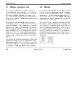
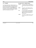
Страница 29: ...follows Key operation on standard model ON OFF This button switches the instrument on and off a short press is used to switch on and a long press switches the instrument off MENU This button is used t...

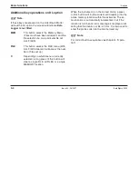
Страница 30: ...hich menu is currently selected a long press of this button will clear a single FILE all FILES or a single MEMORY location When the instrument is in the correct mode a press on this button will log th...

Страница 31: ...Operation 5 AutoSigma 3000 Issue 04 06 2007 5 1...

Страница 32: ...below Also the word SET will appear on the bottom line if the probe temperature has drifted 3 C since the last set routine was carried out If the SET icon appears then the set probe routine should be...

Страница 33: ...t select a frequency of 60 kHz only useable with 12 7 mm probe If it is attempted the instrument will beep and not carry out the change It is then neces sary to move to the PROBE parameter and recall...

Страница 34: ...gma 3000 DL can be set the ref erence block values need to be entered It is recom mended that the STD blocks supplied with the unit are used as these will provide the most effective and ac curate sett...

Страница 35: ...Increment to required level 9 Return to normal mea surement mode Normal measure ment display User reference blocks Can be used to set the AutoSigma 3000 DL provided that STD 1 is within the range 30...

Страница 36: ...is to be between 40 and 45 IACS then STD 1 should ideally be 50 IACS or more and STD 2 should be 35 IACS or less It is possible to set the AutoSigma 3000 DL by using one user reference block and one...

Страница 37: ...t mode with the setting fac tors unaltered If the blocks are used in the wrong sequence or the probe has not contacted the STD s correctly the display will indicate VALUE OUT OF RANGE SE QUENCE WILL R...

Страница 38: ...bilise on the surface of the material to be measured The set probe routine should then be carried out at the tem perature the measurements are to be taken at Place the probe on the surface of the mate...

Страница 39: ...given in application note AN 9603 available from GE Inspection Technologies 5 7 Data logging internal Clearing the entire memory With the instrument in the Measurement mode Step Key Display 1 Open the...

Страница 40: ...st these points will result in the number reverting to the other end of the available range The number of storage locations in the files will depend on the number of files selected see the fol lowing...

Страница 41: ...the display e g 99 8 that is to be logged press SEND If no logging has taken place since the number of files have been set the reading will be logged into loca tion 1 of file 1 Unless a file location...

Страница 42: ...logging to continue or the file location cleared Press MEM to display the contents then a long press on C to clear the file Selecting a file for logging With the instrument in the Measurement mode St...

Страница 43: ...ake place Further logged readings will automatically be placed in location 1 of FILE YY Accessing a file location containing stored data With the instrument in the Measurement mode Step Key Display 1...

Страница 44: ...cation selection 5 8 Customising the operating mode The operating mode of the AutoSigma 3000 DL can be customised to suit a particular measurement pro cedure Menu items can be selected and given a val...

Страница 45: ...r The AutoSigma 3000 DL normally works in the Su pervisor mode where the menu is fully functional it is supplied set to this mode the instrument may also be set to User mode where the menu cannot be s...

Страница 46: ...can be disconnected from the PC In User mode the menu cannot be selected and the settings present when the AutoSigma 3000 DL is con verted will be retained To select Supervisor with the PC connected t...

Страница 47: ...External data handling devices 6 AutoSigma 3000 Issue 04 06 2007 6 1...

Страница 48: ...tically sensed so an external Data Logger can request a reading If printers or PCs etc that use serial RS 232 format are to be connected converter leads are required Product codes 47A004 PC 47A002 Pri...

Страница 49: ...nitiate data out transfer with the File menu set to a single file or ALL FILES H Note For correct handling of transmitted data PCs and print ers should be set to Xon Xoff protocol Sending a single fil...

Страница 50: ...after the press the display will in dicate the transfer After transmission the display will return to ALL FILES H Note To terminate a data transfer when in progress press SEND Display will respond for...

Страница 51: ...rt Instrument Banner Instrument name File Header Various Fields including the file number for the data to follow Readings A list of the measurement values and their locations Statistics Various statis...

Страница 52: ...6 6 Issue 04 06 2007 AutoSigma 3000...

Страница 53: ...Specifications 7 AutoSigma 3000 Issue 04 06 2007 7 1...

Страница 54: ...IACS over range 0 C to 40 C with probe in contact with metal Probes 12 7 mm diameter for 60 kHz and 500 kHz 8 mm probe operates at 500 kHz only Probes are interchangeable with simple customer re setti...

Страница 55: ...icons Calibration Automatically set when set probe sequence is carried out with the probe placed in turn on the calibration blocks The probe thermistor detects when a change in tem perature of more th...

Страница 56: ...further space for extra accesso ries Power Source 3 1 5 V AA size alkaline batteries approx 100 hrs life without backlight Auto Switch Off If the instrument is not used for n minutes or if the batter...

Страница 57: ...Maintenance and care 8 AutoSigma 3000 Issue 04 06 2007 8 1...

Страница 58: ...teries H Note On removal of the batteries the instruments will retain its settings and stored data DL model Memory stor age does not rely on battery power make sure the instrument is switched off befo...

Страница 59: ...Appendix 9 AutoSigma 3000 Issue 04 06 2007 9 1...

Страница 60: ...ordshire AL1 5HL GREAT BRITAIN Phone 44 1727 795500 Fax 44 1727 795400 The AutoSigma 3000 DL is manufactured according to state of the art methods using high quality compo nents Thorough in process in...

Страница 61: ...t Britain GE Inspection Technologies Ltd 129 135 Camp Road St Albans Hertfordshire AL1 5HL GREAT BRITAIN Phone 44 1727 795500 Fax 44 1727 795400 USA GE Inspection Technologies LP 50 Industrial Park Ro...

Страница 62: ...9 4 Issue 04 06 2007 AutoSigma 3000...

Страница 63: ...Index 10 AutoSigma 3000 Issue 04 06 2007 10 1...

Страница 64: ...Alkaline 3 2 Care of 8 2 Installation 3 2 Ni Cad 3 2 C Calibration 5 4 7 3 Calibration standards 3 10 Case 7 4 Case packall 7 4 Cleaning 8 2 Compensation 7 3 Conductivity 3 9 4 2 5 8 7 2 Conductivity...

Страница 65: ...6 3 F File header 6 5 I IACS 3 8 4 2 5 5 Instrument banner 6 5 K Keypad 4 3 L Language changing 3 6 Lift Off 7 3 M Maintenance 8 2 Measurement 4 2 5 2 5 8 6 3 Memory 5 9 6 4 7 4 Accessing file locatio...

Страница 66: ...ng customised mode 5 15 Switching off 5 3 Switching on 5 2 User Supervisor 5 15 Working parameters 5 3 P Parameter setting 3 6 PC 5 15 6 2 Power requirements 3 2 Power source 7 4 Printers 6 2 Probe 4...

Страница 67: ...tions 7 2 Start up 3 7 Statistics 6 5 Supervisor mode 5 15 Support 9 2 T Temperature 3 9 4 2 5 8 Temperature compensation 7 3 Temperature measurement 7 3 U User mode 5 16 User reference blocks 5 5 W W...

Страница 68: ...10 6 Issue 04 06 2007 AutoSigma 3000...

Отзывы: