


3-6
ApexPro™
2001989-301A- draft 1
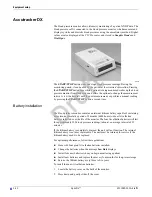
Equipment setup
Verify transmitter/leadwires status
CAUTION
IMPROPER TRANSMITTER/LEADWIRE APPLICATION —
Applying a transmitter and/or leadwire that is not thoroughly dry to
a patient can result in an electrically conductive path being
established and a
Leads Fail
alarm not being provided if leadwires
come off the patient.
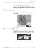
Use the following procedure to verify transmitter/leadwires status before applying to
a patient:
1.
Connect the leadwire to the transmitter, but do not connect the leadwire to a
patient.
2.
Insert batteries in the transmitter and close the battery door.
3.
Wait for the transmitter to start up. The LEDs will first flash rapidly and then
flash slowly twice. Wait until the LEDs are done flashing.
4.
Press the
Verify Leads
button. All the LEDs flash twice to indicate the button
was pushed.
5.
Look for LEDs that light up and stay lit.
If the transmitter is dry, none of the LEDs light up.
If you are using a 5- or 6-leadwire and it is dry, none of the LEDs light up.
If you are using a 3-leadwire and it is dry, only the reference LED will light
up and stay lit.
If the transmitter is wet and an electrically conductive path is established,
some of the LEDs will light up.
6.
If any of the LEDs stay lit, make sure the transmitter is dry. Allow the transmitter
to air dry if other methods are not effective.
Do not attach the transmitter/leadwire to a patient until the transmitter/leadwire is
thoroughly dry.
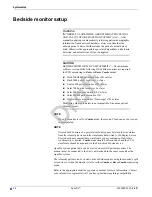
Antenna system
Patient and transmitter status data are dependent on the telemetry system transmission
coverage area. For more information on the telemetry coverage area in your
institution, contact your biomedical or information technology engineers.
202A
Draft


