


8-5
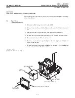
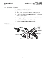
This procedure covers installation of either the right or left drive enable
switch in the handle assembly.
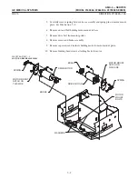
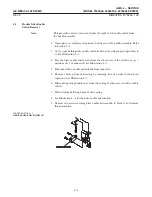
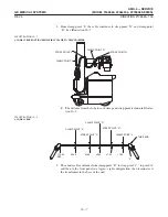
1. See Illustration 8-3, Detail B",for the drive enable microswitch.
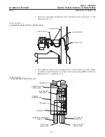
2. Place the drive enable microswitch on its bracket and secure it in place with two
screws.
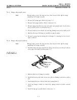
3. Feed drive enable switch leads through back of end casting to connector.
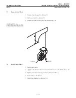
4. Slide end cap alonghandle into position on end casting.
5. Secure end cap to end castingwith four hex socket button head capscrews.
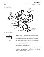
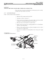
6. Connect drive enable switch leads (blue, yellow or gray) to connector (positions
1 & 2 in connector). See Illustration 8-2.
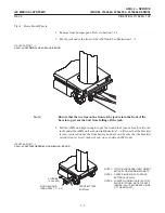
7. Secure enable switch leads and other leads to end castingsupport bracket with
a ty-rap. See Illustration 8-1.
8. Close top cover. Refer to Section 5-6.
Содержание AMX 4+
Страница 1: ...0 0 1 1 2 2...
Страница 2: ......
Страница 3: ...D D D D D D D D D D D D D D D D...
Страница 4: ...D D D D D D D D...
Страница 6: ...iv...
Страница 8: ...vi...
Страница 14: ...xii...
Страница 18: ...xvi...
Страница 32: ...1 14...
Страница 48: ...3 14...
Страница 84: ...5 10...
Страница 106: ...7 12...
Страница 112: ...8 6...
Страница 116: ...9 4...
Страница 131: ......
Страница 132: ...3 2 2 1 0 3 5 0 2 0 4 0 2...


