background image

SECTION 9-Fused  Breakers 

There  are  two  types  of  fused  breakers ;  AKRU 30,  800 

ampere frame  and AKRU 50,  1 600 ampere frame. Except 

for  the  open  fuse  lockout  device  and  the  i ntegrally­

mounted fuses on the u pper studs, the AKRU-30 and -50 
breakers  are  identical  to  the  unfused  AKR-30  and  -50 
models.  Overcurrent  trip  devices  are  the  same  for  both 

types. 

9.1  FUSE  SIZES  AND  MOUNTING 

Table 6 lists the range of fuse sizes available for these 

breakers. The Class 

fuses are mounted as shown in Fig . 

51 . Other than the 800A size, which has a single mounting 

hole per tang , each Class L  fuse tang has two holes sized 
for one-half inch diameter bolts. 

Class 

fuses  rated  300 thru 600A have one  mounting 

hole per tang. The 300, 350 and 400A sizes require copper 
adapter bars  per  Fig.  52. 

All 1f2-1 3  fuse mounting bolts should be torqued to 200-

350 in.

-

lb.  The %-1 1  bolts which attach the C shaped fuse 

adapters to the  breaker studs  should be torqued to 300-
525 in. -lb. 

FIG .  51 - TYPICAL  MOUNTING  CLASS  L 

FUSES 

9.2  SPECIAL 2500A  FUSE  FOR  AKRU-50 

This fuse provides a  melting time-current characteristic 

that coordinates with 1 600A trip devices. Com pared physi­

cally with a 2500A N EMA Class 

fuse, the special fuse is 

more compact (shorter) ; its tangs are specially configured 
and offset to achieve the required  pole-to-pole fuse spac­
i ng ;  a special primary disconnect assembly mounts directly 

on the outboard tang of the fuse.  Considering their unique 

mounting  provisions,  when  replacing these fuses the  fol­
lowing procedure should be adhered to ( Refer to Fig . 53): 

a)  Remove the primary d isconnect assem bly from the 

fuse tang, accom pl ished  by first  loosening  the two keys 
via their holding screw and pulling them u pward and out. 
After the keys are removed ,  pull the d isconnect assem bly 
off  the  end  of  the fuse tang. 

NOT E :  

This  rem o val  does  not  disturb  the 

disconnect's  clamping  force  adjustment. 

b)  Remove the  upper  barrier. 

c)  Detach the inboard end of the fuse by  removing the 

two 1 /2  inch - 1 3  bolts.  A ratchet and socket with a short 

extension will  be  requied. 

d)  Remove the  heat  sink. 

e)  Remove  the fuse. 

f)  I nstall  the  new  fuse  by  reversing  the  disassembly 

procedure.  Ensure that the  mating faces of the fuse  and 
heat sink are clean . 

ADAPTER  BARS  (COPPER) 

FIG.  52 - 300  THRU 600  AMP CLASS J 

FUSE  MOUNTING 

41 

www 

. ElectricalPartManuals 

. com 

Содержание AKR A 30 Series

Страница 1: ... _ Ma ntenance Manual GEK 644598 6 Low Voltage VPower Circuit Breakers Types AKR 30 50 andAKRT 50 G f GENERAL fj ELECTRIC w w w E l e c t r i c a l P a r t M a n u a l s c o m ...

Страница 2: ... Closing 1 1 7 15 Trip Latch Adjustment 32 5 2 1 Alt Control Circuit 12 SECTION 8 33 5 3 Mechanism Operation 13 5 4 Charging Using The 8 0 CONTACT MAINTENANCE 33 Maintenance Handle 13 8 1 Arc Chute Removal Inspection 33 SECTION 6 15 8 2 Contact Adjustment AKA 30 30H AKRU 30 34 6 0 INTERLOCKS 15 8 3 Contact Adjustment 6 1 Racking Mechanism Interlock 15 AKA 50 SOH AKRU 50 36 6 2 Positive Interlock 1...

Страница 3: ...RSATRIP TRIP DEVICE 58 Fuse Selection 12 1 Programmer Unit 58 Table 17 77 12 1 1 Fault Trip Indicators 58 Bell Alarm Contact Rating 12 1 2 Remote Fault Indication 58 Table 18 77 12 1 3 MicroVersaTrip Installation 59 Auxiliary Switch Contact Sequence 12 2 Current Sensors 60 Table 19 77 12 2 1 Replacement of Current Auxiliary Switch Contact Ratings Sensors 63 Table 20 77 12 3 Flux Shifter Trip Devic...

Страница 4: ...BEFORE INSPECTING OR BEGINNING ANY MAINTENANCE WORK ON THE BREAKER IT MUST BE DISCONNECTED FROM ALL VOLT AGE SOURCES BOTH POWER AND CON TROL AND BE IN THE oPEN POSITION A basic inspection should consist of the following a Visual Check Look for dirt grease or other forei material on any breaker parts Check insulating surfac for conditions that could degrade insulating properties cracks overheating ...

Страница 5: ...KR 28 50 AKRU A 30 X 800 AKRU 8 30 AKRU 0 30 AKRU A 50 X 1600 AKRU B 50 AKRU 0 50 Th s dlg t ldenbf es the tnp dev ce type as follows 2 EC DC only 4 ECS 5 SST 50 60 Hertz Only 6 M croVersa Tnp MOUNTING TYPE DRAWOUT SUB AKD 8 STRUCTURE STATIONARY X X X X X X X X X X X X X X X X X X X X X X X X X DEEP FUSED ESCUTCHEON BREAKER X X X X X X X X X X X X X X X X X X X X N Non automabc Inadellbon all non ...

Страница 6: ...ucture needed The conductive members are the studs for exter nal connections movable and stationary contact sets pivots for the movable contacts and provision for mounting the current transformers The interrupter components are in addition to the arcing contacts the arc runners mounted on the back base and the removable arc quencher assemblies In addit1on to these basic components a breaker may be...

Страница 7: ... r r FIG 2 Electrically Operated AKR SB 30 FIG 3 Fused Breaker AKRU 60 30 FIG 4 Drawout Breaker 7 w w w E l e c t r i c a l P a r t M a n u a l s c o m ...

Страница 8: ...CERAMIC ARC CHUTES 2 5 TRIP DEVICE There are 4 types of solid state direct acting self powered trip device systems associated with AKA break ers These systems are for AC applications only For DC applications an electro mechanical system is available The trip device system is identified by the first middle digit in the breaker s nameplate designation as follows AKA B 30 L Trip device code number pe...

Страница 9: ...KAT SOH 800 AKAU 30 1600 AKAU 50 800 DC AKA 30 2000 DC AKA 50 With 40 800 Amp Trip Coils With 200 2000 Amp Trip Coils consult Factory For Application Data 3c INTERRUPTION RATING RATED KA RMS SYMMETRICAL MAXIMUM WITH WITHOUT VOLTAGE INSTANTANEOUS INSTANTANEOUS 60HZ AC TRIP TRIP 635 508 30 30 254 42 635 508 42 42 254 635 42 42 508 50 50 254 65 635 50 50 508 65 65 254 635 508 65 65 254 635 50 50 508 ...

Страница 10: ...nterchangeability In general drawout breakers of the same type and rating are interchangeable in their equipment compartments drawout breakers of different frame sazes are not anter changeable To prevent inserting the wrong type breaker into a drawout compartment suitable reJectaon hardware is affixed to each breaker and ats compartment Fagure 7 shows a typacal re1ectaon bracket whtch ahgns wath a...

Страница 11: ... fully charged As this fully charged position is reached mechanically operated switches F and G reverse their shown position the G switch deenergizing the motor and the F switch estab lishing a circuit to the X relay At the same time a mechanical prop is positioned to prevent the discharge of the fully charged closing spring With the closing spring propped fully charged the breaker is ready for cl...

Страница 12: ...s the closing solenoid Thi removes the prop releasing the closing springs to close the breaker The F cutoff switch is only installed on breakers using D C control voltage The anti pump function is obtained through the nor mally closed K relay contact in the motor circuit If a close signal is maintained after the breaker has tripped open automatically the K relay Is energized preventing the motor f...

Страница 13: ... linkage This allows the secondary latch to pivot against the front frame as shown leaving a gap between the trip latch and secondary latch roller The secondary latch is now in a position to engage with both the top latch and cam roller The breaker closes when the closing spring discharges and rotates the cam against the cam roller The toggle linkage is fully extended pivoting the secon dary latch...

Страница 14: ... see Fig 1 2 This holds the closing spring in a charged condition Rotate the camshaft using the maintenance handle until the ratchet assembly s roller engages with the prop Do not drive the roller against the prop with undo force The breaker can now be closed by removing the prop from thr roller This is done by manually activating the closin solenoid s armature Push the solenoid s armature into it...

Страница 15: ...r must be slid to the right to gain access to the drive shaft When the breaker is in the CLOSED position a link en gages the RACKING SCREW cover preventing it from being opened This link is driven by the motion of the OPEN CLOSED indicator as shown in Fig 15 The TRIP button also engages with the RACKING SCREW cover in both the OPEN and CLOSED positions Therefore the TRIP button must be pushed in b...

Страница 16: ...in anached to the crank moves through the slot rn the linkage The hnkage IS connected to a leverwh1ch engages with a prn on the clos1ng solenoid armature hnkage When the rack1ng mechantsm approaches the DISCONNECT 16 FIG 1 6 POSITIVE INTERLOCK position the crank s pin reaches the end of the slot in the linkage Continued motion of the racking mechanism causes the linkage to rotate the lever which m...

Страница 17: ...ttached to the racking mechanism shaft is connected to the blocking plate through a link As the shaft turns the blocking plate rotates holding the cover open in the DISCONNECTED position but allowing it to close in the TEST and CONNECTED positions FIG 18 DISCONNECT POSITION INTERLOCK 6 5 PADLOCKS Provisions are made in all breakers to use padlocks to prevent the breaker from being closed For non T...

Страница 18: ...ad locksmay be used to lockthe inner house in the discon nected position When the breaker is in the CLOSED position the flywheel assembly is away from the lever The lever is spring loaded and rotates clockwise causing its pin to block the lock bolt extension r r 4 J J 3 _ I 5 6 FIG 1 9 KEY INTERLOCK STATIONARY BREAKERS SECTION 7 Breaker Maintenance 18 SAFETY PRECAUTION WARNING BEFORE INSPECTING OR...

Страница 19: ... by a single 1 35 degree clockwise handle stroke or up to four multiple strokes of lesser swing The following adjustment procedures should be performed using the single stroke method By so doing proper multi stroke operation is assured Therearetwo handleadjustment linkage designs in use The adjustment linkage connects the handle assembly to the chain drive mechanismwhich turns the cam shaft The le...

Страница 20: ...DISCHARGED position and the spring at its minimum extension Remove the hex head boltonly do notremoveor loosen the slotted head screw shown in Fig 21 Removal of the slotted head will cause the closing spring to become dis engaged from the camshaft with considerable force Verify that this screw remains tightened during the slow close operation After the bolt is removed use the maintenance handle to...

Страница 21: ...SEMBLY FIG 24 PARTIAL PRIMARY DISCONNECT ASM The BOO ampere breakers use four primary disconnect fingers per phase The 1 600 and 2000 ampere breakers use eight fingers per phase Fig 22 shows a line and load end disconnect assembly The line end disconnects on fusible breakers have the spring pointing downwards otherwise they are identical FIG 23 PARTIAL PRIMARY DISCONNECT ASM FIG 25 PARTIAL PRIMARY...

Страница 22: ...ntacts are opened or closed as the breaker is opened or closed B contacts are the reverse of this The auxiliary switch is mounted on the upper side of the mechanism frame as shown in Fig 27 A crank on the main shaft operates the switch through an adjustable link which connects it to the switch crank 22 _l_ J L_ _ J ________ i 11 I I r j __ _ ___ F L J I t FIG 26 PRIMARY FINGER ADJUSTMENT FIG 27 AU...

Страница 23: ...lock will be supplied This is required for clearance in this case the buffer assembly must be taken off disassembled and remounted together with the number two undervoltage device Before disassembling the original buffer carefully measure the distance between the faces of the threaded members as shown in Fig 31 and set this dimension carefully on the new assembly Refer to the breaker wiring diagra...

Страница 24: ...rmature where Its constant radius Is closest to the rivet FIG 32A UNDERVOLTAGE DEVICE If excessive clearance or binding exists loosen the screws holding the magnet assembly to the frame and move the magnet up or down as necessary Tighten the screws to 27 to 32 in lbs 2 The air gap between the armature and magnet with the undervoltage device de energized should be 25 inches Check the gap by inserti...

Страница 25: ...ly mounted in the switchgear and the undervoltage device is mounted on the breaker Table S lists the catalog numbers available INSERT WIRE GAGE FIG 320 POSITIVE TRIP CHECK If the a c control voltage is any voltage other than 2081240V ac a control power transformer also remotely mounted with respect to the breake must be used This must have a minimum rating of 100 volt amperes When installed the vo...

Страница 26: ... located in the opening in the lower part of the escutcheon This breaker door must be opened to gain access to it MAIN SHAFT 2EM iCLOSED l I I 1 _ I Ti I I I I HOLD IN J_ l I FIG 34 ELECTRIC LOCKOUT BY PASS 26 FIG 33 ELECTRIC LOCKOUT DEVICE 7 11 BELL ALARM This device is used to give a remote indication of the breaker s having tripped open through the action of one of Its automatic protective devi...

Страница 27: ... A 187 inch depression of the TRIP button must not trip the breaker but a 375 inch must trip the breaker and the side latch W RELAY X RELAY OR K RELAY 7 11 3 REPLACEMENT The bell alarm Is mounted on the right hand side of the breaker at the rear of front frame It is located under the mechanism s main shaft The bell alarm is removed by passing it through a cutout in the rear bend of the front frame...

Страница 28: ... for slow dosing as described earlier Tum the camshaft using the maintenance handle until the roll pin is well started tum the camshaft to gain enough space for the roll pin to clear the breaker frame Before removing the ratchet note the position of the ratchet s roller or mar1 the ratchet s hub and the camshaft When replacmg the ratchet be sure It Is oriented with respect to the camshaft as it wa...

Страница 29: ...perates the switches A very thin open end 5 8 inch wrench will be needed to loosen or tighten the nuts which fasten the switches to the bracket 7 1 3 DRAWOUT MECHANISM The drawout mechanism shown in Fig 38 moves the breaker through the DISCONNECTED TEST and CON NECTED positions Fig 39 shows how the drawout mechanism is mounted to the breaker As the racking handle is turned the internally threaded ...

Страница 30: ...SECTION 7 Breaker Maintenance Cont FIG 38 DRAWOUT MECHANISM DETAILS FIG 39 RACKING MECHANISM INSTALLED 30 w w w E l e c t r i c a l P a r t M a n u a l s c o m ...

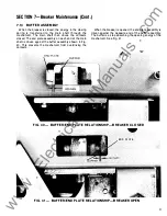
Страница 31: ...n shaft is driven against the buffer assembly shown in Fig 40 This prevents the mechanism from overdriving the contacts When the break r is opened the end plate assembly is driven against the opposite end of the buffer assembly The buffer is a stop absorbing the opening energy of the mechanism See Fig 41 FIG 40 BUFFER END PLATE RELATIONSHIP BREAKER CLOSED FIG 41 BUFFER END PLATE RELATIONSHIP BR EA...

Страница 32: ...en a 040 maximum clearance can exist between either of the end plate assemblies and the buffer bolt heads as shown If a larger clearance exists close it up by unscrewing the buffer assembly involved Fig 42 shows a buffer assembly prior to being installed in a breaker The dimensions given establish the number of spacers that are used 7 15 TRIP LATCH ADJUSTMENT The reset position of the trip latch i...

Страница 33: ...s of arc chute construction used on the 800 thru 2000 ampere breakers They are the ceramic type shown in Fig 5 and the molded type shown in Fig 6 The ceramic type uses a two piece porcelain frame to enclose its internal parts The molded type uses a one piece glass filled polyester frame The 800 ampere arc chute is different from the 1600 and 2000 ampere arc chute which are identical Therefore the ...

Страница 34: ...ion 5 3 3 Select one pole and using a flat or wire feeler gage measure the gap between the top contact and its pivot stud as shown in Fig 45 As necessary adjust the gap to 0 060 0 020 inch by turning the wipe adjustment nut shown in Fig 46 4 Once the gap dimension is set verify that the torque required to just tum the adjustment nut is greater than 40 in lbs If less torque is required carefully ad...

Страница 35: ...SECTION 8 Contact Maintenance Cont FIG 448 AKR 30H 800 AMP CONTACT STRUCTURES 35 w w w E l e c t r i c a l P a r t M a n u a l s c o m ...

Страница 36: ...eaker with tl e insulation held in place Examine the insulation to make sure it over hangs below the in termediate contacts but not enough to coverthe main con tacts 5 Attach a continuity checker bell set light or ohm meter between the upper and lower stud The checker should indicate continuity exists 6 Facing the breaker tum the wipe adjustment stud shown in Fig 47 clockwise until the checker ind...

Страница 37: ...isually by removing the arc quenchers closing the breaker and verifying that all eight stationary main contacts are lifted off their stops Should wipe ad justment appear necessary proceed as follows 1 Open the breaker 2 Arrange the breaker for slow closing 3 Selecting one pole drift out the coupling pin and detach the driving link from the movable contact arms 4 Screw the driving link completely i...

Страница 38: ...nfigurations shown in Figs 44 47 or 48 Fig 49 shows the stationary contacts and how they differ from one another The 800 amp main and arcing contacts are rectangular but the arcing contacts have two of their corners notched The 1600 2000 amp main and intermediate contacts are rectangular but the main contacts have two of their corners notched The inter mediate contacts have all four corners notche...

Страница 39: ...tionary contacts The stationary intermediate and main contacts are replaced just like the stationary contacts on the 800 ampere breakers Refer to steps 2 3 in Section 8 6 Referring to Fig 50 the stationary arcing contacts are replaced as follows 1 Remove the arc runner and the flat insulation assembled underneath the arc runner It is secured with four screws When removing the lower screws use care...

Страница 40: ...SECTION 8 Contact Maintenance Cont FIG SOB ARC RUNNER REMOVED 40 FIG SOC ARCING CONTACT PIVOT REMOVED w w w E l e c t r i c a l P a r t M a n u a l s c o m ...

Страница 41: ...MA Class L fuse the special fuse is more compact shorter its tangs are specially configured and offset to achieve the required pole to pole fuse spac ing a special primary disconnect assembly mounts directly on the outboard tang of the fuse Considering their unique mounting provisions when replacing these fuses the fol lowing procedure should be adhered to Refer to Fig 53 a Remove the primary disc...

Страница 42: ...BREAKER FUSE TANGS BREAKER STUD POSITIONED ON TOP OF BREAKER STUD 1TANG BOLT HOLES IN USE 0 0 l 2500A FUSE CAT NO GF9F2500 AK 0 0 FOR THIS POLE ONLY FUSE IS ROTATED 1 80 TO POSITION TANG BENEATH STUD 0 0 PRIMARY DISCONNECT ASSEMBLY SEE FIG 1 3 MOUNTS DIRECTLY ON OUTBOARD FUSE TANG FIG 54 AKRU 50 2500A FUSE TANG POSITIONS TABLE 6 FUSES FOR AKRU BREAKERS NEMA Gould Shawmut Fuse Breaker Cat Nos Clan ...

Страница 43: ...Refer to Fig 56 a Back off tripping rod so that it will not hit the trip paddle when a solenoid is activated b Using the maintenance handle close the breaker c Manually close the Left pole armature Screwtripping rod forward until it moves the trip paddle enough to open the breaker Add two full turns d Close the breaker e Manually close the Left pole armature again The breaker must open and the res...

Страница 44: ...ION 9 Fused Breakers Cont 44 TRIP PADDLE I ARMATURE FIG 56A DETAILS ll I I _ _ ___ _ r 1 RESET BUTION FIG 568 INSTALLED TYPE A OR 8 BREAKER OFLO DEVICE w w w E l e c t r i c a l P a r t M a n u a l s c o m ...

Страница 45: ...uated by the short time and instantaneous elements and the thirdforground fault The latter is omitted on units without ground fault FIG 57 SST BLOCK DIAGRAM OVOI CWI I TAIIGET I I I I I 1 CIM IIIT I TMW I Each target pops out when its associated trip element operates to trip the breaker After a trip the popped target must be reset by hand However neglecting to reset does not affect normal operatio...

Страница 46: ...eries with a companion pnmary winding on a ground differential transformer mounted in the programmer unit Its secondary output is zero so long as there is not ground current Application of the Ground Fault element on 4 wire sys tems w1th neutral grounded at the transformer requires the add1hona1 separately mounted neutral sensor Fig 61 mserted 1n the neutral conductor its secondary is con nected t...

Страница 47: ...H TAP BOARD 600 1600 A 300 800 A 100 3 00 A FIG 61 SST NEUTRAL SENSORS REAR VIEW AKR 50 BREAKER MOUNTED EQUIPMENT MOUNTED FIG 62 NEUTRAL SENSOR SECONDARY DISCONNECT BLOCKS 47 w w w E l e c t r i c a l P a r t M a n u a l s c o m ...

Страница 48: ... tighten the Allen head screws to 250 10 in lbs Tighten th6 clamping bolt as follows AKA 30 30H 120 10 in lbs AKA 50 50H 470 1 0 in lbs AKRT 50 50H 470 1 0 in lbs 10 3 FLUX SHIFT TRIP DEVICE The Flux Shift Trip device is a low energy elec tromagnetic device which upon receipt of a trip signal from the programmer unit trips the breaker by actuating the trip shaft The mounting arrangement of this co...

Страница 49: ...unit should be replaced When making the electrical connector to the replacement unit it is recommended that the brea ker harness be cut at some convenient point and the new actuator leads solder spliced thereto The preferred method is to remove the flux shifter leads from the AMP connector using the AMP extrac tion tool Cat No 305183 as follows TRIP PADDLE C RANK BREAKER CLOSED POSITION SIDE VIEW ...

Страница 50: ...ew Top view 1 Actuator 2 Trip rod adjuster end 4 Trip shaft 5 Actuator arm 3 Trip paddle 6 Reset linkage FIG 65 FLUX SHIFT TRIP DEVICE COMPONENTS TRIP PADDLE IN w CHANISW RESET POS I T ION FIG 66 TRIP ROD ADJUSTMENT w w w E l e c t r i c a l P a r t M a n u a l s c o m ...

Страница 51: ...l transformer will generate an unwanted ground fault output signal which will trip the breaker This can be nullified either by a testing two poles of the breaker in series or b using the Ground Fault Defeat Cable as shown in Fig 71 This special test cable energizes all the primary windings of the differential transformer in a self cancelling series parallel connection so that its secondary output ...

Страница 52: ...RCUIT THE CURRENT SENSORS ALLOWING DANGER OUS AND DAMAGING VOLTAGES TO DEVELOP Test scope 1 Verify the time current characteristics and pickup calibration of the various trip elements 2 Verify operation of the SST target indicators on pro grammer units so equipped 8 Complete Trio Device Svstem For these tests the programmer un1t must be mounted on the breaker and connected to 1ts wiring harness Te...

Страница 53: ...sensors are identical 1 0 5 SST CABLING DIAGRAMS c Verify that the harness connections to the sensors meet the polarity constraints indicated by the cabling dia gram i e white wire to COMMON black wire to TAP d On Ground Fault breakers serving 4 wire loads check that the neutral sensor is properly connected see cabling diagram Fig 70 In particular 1 Verify that the neutral sensor has the same rati...

Страница 54: ...ABLING DIAGRAM SST WITH GROUND FAULT ON 3 WIRE LOAD 4 WIRE LOAD FLUX SHIFT TRIP DEVICE PROGRAMMER UNIT r o H 48V de J2 l ok f k TO SCR ANODE BLACK WHITE BLACK WHITE BLACK WHITE BLACK HARNESS CONNECTOR PROGRAMMER CAMP 201298 1 1 CONNECTOR CAMP 201217 1 FIG 70 CABLING DIAGRAM SST WITH GROUND FAULT ON 4 WIRE LOAD w w w E l e c t r i c a l P a r t M a n u a l s c o m ...

Страница 55: ...u L _ F n i H u L _ K 1t r L I I I I N M I I I I p R oo J FEMALE END PROGRAMMER UNIT r r I l H 0 t 3 f ti t 3 r o I f H I H a l L_J L _ _ _j ANY SST PROGRAMMER UNIT WITH GROUND FAULT ELEMENT FIG 71 CABLING DIAGRAM WITH GROUND FAULT DEFEAT CABLE INSERTED BETWEEN BREAKER HARNESS AND SST PROGRAMMER UNIT FOR USE DURING SINGLE PHASE HIGH CURRENT LOW VOLTAGE TESTING 55 w w w E l e c t r i c a l P a r t ...

Страница 56: ...ratings which span the same range as SST see Fig 74 3 Neutral sensors are not required because there is no Ground Fault function In all other respects the ECS Trip device system operates and can be treated identically to SST This in cludes circuitry size construction component loca tion programmer unit set points performance characteristics operating range quality reliability and the flux shift tr...

Страница 57: ... 800 1200 1600 2000 Pickup tolerance is 9 Pickup tolerance is 10 Time delay shown at 600 of long time pickup setting 6L at lower limit of band Time delay shown at lower limit of band TABLE 1 0 SENSOR RESISTANCE VALUES Ampere Rating 100 150 225 300 400 600 800 1200 1600 2000 1 1 1 ECS CABLING DIAGRAM c A A 4 rf 1 I I I I I I A I H I I I a I H I I I c L v f J v r r r Resistance In Ohms between Termi...

Страница 58: ...G TIUE PICKuP OELAV f SHORT TIU PICKuP DELAY t ST TAHEOVS PICKuP 1 GAQvO IO Ac T POC uP 0 LA f REGc A i f O lltlC A SuPI l I I I I I I I I 0VERLOAO ARGET T T SHORT oRCUIT ARGE T I T I I I I L _ _ _ _ _ _ _ _ _ __ 58 FIG 76 MICROVERSATRIP BLOCK DIAGRAM 12 1 1 FAULT TRIP INDICATORS The optional fault trip indicators are similar to the SST indicators They are mechanical pop out type for identify ing ...

Страница 59: ... They provide the necessary alignment for the connector engagement The locking lever engages with the pin which is assembled to the programmer frame and secures the pro grammer to the mounting bracket There are two programmer mounting designs in use The difference in the designs is in the operation of the locking lever see Fig 82 Installation using each design Is as follows a Insert the guide pins...

Страница 60: ...nstan taneous MicroVersaTrip option H option is required Fig 84 shows an H option phase sensor When the H option phase sensor is installed there are four leads connected to It two flag terminal connections additional winding and two screw terminal connections ampere rating There is no polarity associated with the flag ter minals Fig 94 shows the connections for the additional H option windings Fig...

Страница 61: ...illed TJIPPed ol Sensor Multiple Del8y llulmum s n or Seneora CurTent ol CurTent f _ Aallng Aallng Aallng Seconds Size Amps _ f A8tlng X C 100 1 50 100 1 50 225 300 5 6 7 8 9 2 5 5 AKR 30 800 225 300 or 8 85 9 1 0 1 1 10 21 400 800 300 400 95 1 0 C 800 800 800 X 300 400 300 400 600 800 AKR 50 1 600 600 600 01 1200 1800 600 800 1200 1800 800 1200 600 1200 AKRT 50 2000 1600 2000 1600 2000 1200 1600 ...

Страница 62: ...oVersaTrip Trip Device Cont 62 TAPPED COMMON TERMINAL FIG 83 MICROVERSATRIP M PHASE SENSORS t G C t a E FIG 84 H Optlon Phase Sensor FIG 85 TYPICAL NEUTRAL S ENSOR w w w E l e c t r i c a l P a r t M a n u a l s c o m ...

Страница 63: ... connector from the contact pivot block c Loosen the clamping bolt and remove the stud con nector Uft out the sensor and its tap terminal board The sensor may be prevented from slipping off the sen sor stud by adjacent accessories If this exists the sensor stud must be removed from the breaker base The stud assembly is secured to the base with four bolts which are accessible from the rear of the b...

Страница 64: ...at the circuit breakf can be opened and closed normally from the test posltior attention can be directed to the trip device proper Testing is performed by either of two methods 1 Conduct high current single phase tests on the breaker using a high current low voltage test set NOTE Forthese single phase tests special connec tions must be employed forMicroVersaTrip breakers equipped with Ground Fault...

Страница 65: ...sufficient to trip the breaker Similarly discontinuity between any sensor and the programmer unit can cause a false trip signal If nuisance tripping is encountered on any breaker whose MicroVersaTrip components have previously demonstrated satisfactory performance via the TVTS1 Test Set the sensors and their connections should be closely scrutinized After disconnecting the breaker from all power s...

Страница 66: ...AMMER AMP 1_350356 9 CONNECTOR LOAD FIG 89 CABLING DIAGRAM MICROVERSATRIP WITHOUT GROUND FAULT A B c A A A BREAKER BAcK FRAME r A b A 1 LEFT POLE I I CURRENT SENSOR I FLUX SHIFT TRIP DEVICE I I_ J r r r LOAD HARNESS CONNECTOR AMP 1 350356 9 PROGRAMMER UNIT PROGRAMMER CONNECTOR FIG 90 CABLING DIAGRAM MICROVERSATRIP WITH GROUND FAULT ON 3 WIRE LOAD w w w E l e c t r i c a l P a r t M a n u a l s c o...

Страница 67: ...RE LOAD 4 WIRE LOAD 1 1 1 BREAKER r _ 4 I BACK FRAME b b I LEFT POLE I CURRENT FLUX SHIFT TRIP DEVICE SENSOR I lf 4 H 1111 h I t I I EQUIPMENT MOUNTED I NEUTRAL SENSOR I A I NEUTRAL I SENSOR 1 DISCONNECT I trt t H 1 1 N I PROGRAMMER UNIT r v v v A a c HARNESS PROGRAMMER CONNECTOR CONNECTOR AMP 1 350356 9 LOAD FIG 92 CABLING DIAGRAM MICROVERSATRIP WITH GROUND FAULT ON 4 WIRE LOAD BREAKER REVERSE FE...

Страница 68: ... L _ _ _j ANY MICROVERSATRIP PROGRAMMER UNIT WITH GROUND FAULT ELEMENT FIG 93 CABLING DIAGRAM WITH GROUND FAULT DEFEAT MODULE INSERTED BETWEEN BREAKER HARNESS AND MICROVERSATRIP PROGRAMMER UNIT FOR USE DURING SINGLE PHASE HIGH CURRENT LOW VOLTAGE TESTING r r r LOAD YEUOW YELLOW YEUOW YELLOW YEUOW HARNESS CONNECTOR PROGRAMMER UNIT PROGRAMMER CONNECTOR FIG 94 PARTIAL CABLING DIAGRAM H OPTION WINDING...

Страница 69: ... J AMP 1 350239 9 AMP 1 350246 9 AMP 1 350242 9 AMP 1 350235 9 FIG 95 CABLING DIAGRAM REMOTE FAULT I NDICATION PROGRAMMER SECONDARY DISCONNECT EQUIPMENT BREAKER SHORT TIME INPUT _ o E f Q i Q t _ SHORT TIME OUTPUT o E t o IKJ t GROUND FAULT INPUT _ C GROUND FAULT OUTPUT E i o AMP AMP 1 350239 9 1 35024 9 MICRQ VERSA TRIP PROGRAMMER I I I _ _ _j FIG 98 CABLING DIAGRAM ZONE SELECTIVE INTERLOCK 69 w ...

Страница 70: ... 1 GES0010 EC 2 2A 1A 3 GES001 1 EC 2 2A 1 8 3 GES0012 EC 2 2A 1C 3 FIG 98 EC TRIP DEVICE TABLE 1 5 EC DEVICE TRIP CHARACTERISTICS l oftg Time Shott Time ln wrtllneoue Trip Device Pickup o y up Deley Pldlup I lA MAX l t 38 MC I Ot IIX 80 160 X 1 1 81 INTER c21 7 t 1 8 Me 12X EC 2A I I to II 15X 0t Ot I I C I MIN 3 3 8 2 MC 80 250 I I AI MAX 30 MC 12AI MAX 23 MC Ot 2 5X Ot 80 1 60 X l l l 1 INTER I...

Страница 71: ...SECTION 13 EC Trip Device Cont _ fi _1_ I 2 FIG 99 OVERCURRENT TRIPPING DEVICE EC 2A r 71 w w w E l e c t r i c a l P a r t M a n u a l s c o m ...

Страница 72: ...ment screw 4 may be turned by in sertmg a Ph1ll1ps head screwdriver through the hole in the front of the case II it 1s des red to relate the linkage setting to the index marks on the hnkage it will be necessary to remove the case Th1s may be done by removing the two mounting screws one on each s1de of the case which may be taken off without disturbing the tnp unit itself 72 13 1 2 INSTANTANEOUS LO...

Страница 73: ...PING The armature 1 0 is restrained by the calibration spring 1 1 After the magnetic force produced by an overcurrent condition overcomes this restraining force the armature movement is fur ther retarded by the flow of silicone oil in a dashpot which pro duces an inverse time delay characteristic The mechanism is shown on Fig 101 Right Side VIew Showing Long Time Delay Mechanism Front VIew Showing...

Страница 74: ...load condition FIG 1 02 CHECKING TRAVEL DISTANCE OF SERIES OVERCURRENT TRIPPING DEVICE 74 1 3 3 POSITIVE TRIP ADJUSTMENT Before attempting any checks or adjustments on breaker wi EC trip devices the breaker mechanism and trip latch should checked to assure their proper functioning so that the breakt trip shaft is free of high friction loads The trip latch of the breaker should also be checked for ...

Страница 75: ...hich tends to rotate the armature counterclockwise The calibration spring also tends to rotate the armature in the same direction This torque causes the armature to rest against the stop screw 12 attached to a bearing plate on the right side of the device H the current through the series coil 2 is reversed the ar mature 10 tends to move in the clockwise direction against the restraint of the calib...

Страница 76: ... removed and replaced by following the pro cedure outlined for replacing the series overcurrent device See Section 1 3 6 For wiring see Fig 1 03 1 3 5 SWITCHETTE FEATURE The switchette is operated by the long time delay function Its purpose is to provide a set of contacts that will close before an overload occurs This device will not trip the breaker on over load it will trip on instantaneous only...

Страница 77: ...4 024 90 015 01 5 180 090 052 090 052 95 047 032 050 029 050 029 1 75 032 01 8 064 036 064 036 1 90 035 023 CONTROL CLOSING RELAY X SOLENOID Rated Amps J Rated Amps S a Inrush Sealed 10 Inrush Open Closed u Open E 4 1 4 1 38 5 2 1 05 1 05 100 1 75 53 53 200 88 1 0 14 2 6 1 0 1 5 98 2 2 6 85 1 27 1 1 45 063 1 5 55 083 1 77 1 2 3 86 76 60 50 07 1 3 50 08 1 96 1 1 3 42 64 54 TABLE 19 AUXILIARY SWITCH...

Страница 78: ...1 7 480 25 380 508 3 5 3 3 11 575 60 475 625 2 8 2 5 16 575 50 475 625 5 1 4 7 14 575 25 475 625 3 1 3 0 10 TABLE 22 COIL RESISTANCE DC OHMS 25 C Nominal Control Anti Pump Control Shunt Voltage Frequency Hz Relay w Relay x Trip Undervolblge 24V DC N A N A 3 64 48V DC 802 1 2 1 1 240 1 25V DC 5000 1 1 9 64 1 600 250V DC 1 6400 476 260 6700 1 20V 60 450 54 3 9 25 4 1 20V 50 450 75 7 15 33 1 20V 25 1...

Страница 79: ...5 120 VAC 102 106 1 00 1 06 36 72 208 VAC 156 1 76 136 176 62 1 25 240 VAC 206 212 200 21 2 72 144 380 VAC 285 323 247 323 1 14 223 480 VAC 360 408 312 408 144 288 575 VAC 431 488 374 488 1 73 345 TABLE 24 TIME DELAY UNDERVOLTAGE DEVICE SETTINGS DELAY PICK UP RANGE UVR INSTALLED DROP OUT UNIT UVR ONLY MECHANISM RESET RANGE VOLTAGE VDC NO PICK UP PICK UP 125 VDC 77 85 50 90 95 250 VDC M IN IMUM 208...

Страница 80: ... sw s Dv pa ses U o 0 ro l Como Outside the U S wr te ConstructiOn EQuipment Export Operat on 4 1 1 Theodore Fremd Ave Aye NY 10580 GEK 644598 PSE 1 285 For further 1nformat1on call or wnte your local General Electnc Sales OffiCe or General Electnc 01stnbut1on EQuipment 4 1 Woodford Avenue Pla1nv1lle CT 06062 G E N E R A L fj E L E CT R I C w w w E l e c t r i c a l P a r t M a n u a l s c o m ...

Страница 81: ... GEK 644590 Maintenance Manual Low Voltage Power Circuit Breakers Types AKR 30I50 and AKRT 50 w w w E l e c t r i c a l P a r t M a n u a l s c o m ...

Страница 82: ...1 7 15 Trip Latch Adjustment 32 5 1 Manual Closing 1 1 5 2 Electrical Closing 1 1 SECTION 8 33 5 2 1 Alternate Control Circuit 1 2 8 0 CONTACT MAINTENANCE 5 3 Mechanism Operation 13 33 5 4 Charging Using The 8 1 Arc Chute Removal Inspection 33 Maintenance Handle 13 8 2 Contact Adjustment AKR 30 30H 30L AKRU 30 34 SECTION 6 1 5 8 3 Contact Adjustment AKR 6 0 I NTERLOCKS 15 50 50H AKRU 50 AKR 30L 36...

Страница 83: ... Epic MicroVersaTrip Installation 71 Current Sensors 71 Replacement of Current Sensors 74 Flux Shifter Trip Device 74 Troubleshooting 74 Resistance Values 74 False Tripping Breakers Equipped With Ground Fault 75 Cabling Diagrams 75 Page SECTION 1 4 77 1 4 0 MICROVERSATRI P PLUS AND MICROVERSATRIP PM TRIP UNITS 77 1 4 1 Trip Unit 77 1 4 2 Testing 78 1 4 3 Product Structure 78 1 4 4 Trip Unit Remova...

Страница 84: ... OR BEGINNING ANY MAINTENANCE WORK ON THE BREAKER IT MUST BE DISCONNECTED FROM ALL VOLT AGE SOUR CES BOTH POWER AND CON TROL AND BE IN THE OPEN POSITION A basic i nspection should consist of the following a Visual Check Look for dirt grease or other foreign material on any breaker parts Check insulating surfaces for conditions that could degrade insulating properties cracks overheating etc Also ch...

Страница 85: ...KR 2S 30 AKR 2A 50 X 2000 AKR 28 50 X DC AKR 2D 50 X X AKR 2S 50 AKRU A 30 X 800 AKRU 8 30 X AKRU D 30 X X AKRU A 50 X 1 600 AKRU 8 50 X AKRU D 50 X This digit identifies the trip device type as follows 2 EC DC only 4 ECS 5 SST 50 60 Hertz Only 6 MicroVersa Trip N Non automatic In addition all non automatic 250VDC breaker types carry the suffix letter D after the frame number e g AKR NB 500 7 RMS ...

Страница 86: ...act sets pivots for the movable contacts and provision for mounting the current transformers The interrupter components are in addition to the arcing contacts the arc runners mounted on the back base and the removable arc quencher assemblies In addition to these basic components a breaker may be equipped with any combination of many accessories and interlocking devices Breakers may also differ in ...

Страница 87: ...FIG 2 Electrically Operated AKR 70 30 FIG 3 Fused Breaker AKRU 60 30 PRIMARY 7 FIG 4 Drawout Breaker 7 w w w E l e c t r i c a l P a r t M a n u a l s c o m ...

Страница 88: ...C CHUTES 2 5 TRIP DEVICE There are several types of solid state direct acting self powered trip device systems associated with AKA breakers These systems are for AC applications only For DC applications an electro mechanical system is available The trip device system is identified by the first middle digit in the breaker nameplate designation as follows AKA i 8 30 1 __ _Trip device code number per...

Страница 89: ... 30 1 600 AKRU 50 800 DC AKR 30 2000 DC AKR 50 With 40 800 Amp Trip Coils 2With 200 2000 Amp Trip Coils 3Consult Factory For Application Data 3 INTERRUPTION RATING RATED KA RMS SYMMETRICAL MAXIMUM WITH WITHOUT VOLTAGE INSTANTANEOUS INSTANTANEOUS 60 HZ AC TRIP TRIP 635 30 30 508 254 42 635 42 508 42 254 50 635 50 50 508 65 65 254 635 42 42 508 50 50 254 65 635 50 50 508 254 65 65 635 508 65 65 254 ...

Страница 90: ...s any responsibility for prac tices which deviate from the following 1 ALL CONDUCTORS M UST BE ASSUMEDTO BE ENER GIZED UNLESSTHEIRPOTENTIALHASBEEN MEASURED AS GROUND AND SUITABLE GROUNDING CONDUC TORS HAVE BEEN APPLIED TO PREVENT ENERGIZING Many accidents have been caused by back feeds from a wide variety of sources 2 Although interlocks to reduce some of the risks are provided the individual s ac...

Страница 91: ...ted with primary current injection Others can be adequately tested using test sets Specific calibration instructions on particular devices typically are provided by supplied instruction books Instruction books supplied by manufacturers address components that would normally require service or main tenanceduring the useful life ofthe equipment However they can not include every possible partthat co...

Страница 92: ...id CC This removes the prop releasing theclosing springsto closethe breaker The F cutoff switch is only installed on breakers using D C control voltage The anti pump function is obtained through the nor mally closed K relay contact in the motor circuit If a close signal is maintained after the breaker has tripped open automatically the K relay is energized preventing the motor from charging the cl...

Страница 93: ...h item 1 4 to pivot against the front frame as shown leaving a gap between the trip latch and secondary latch roller The secondary latch is now in a position to engage with both the trip latch and cam roller The breaker closes when the closing spring discharges and rotates the cam item 3 against the cam roller item 5 The toggle linkage is ful ly extended pivoting the secon dary latch from the fron...

Страница 94: ... 2 This holds the closing spring in a charged condition Rotate the camshaft using the maintenance handle until the ratchet assembly roller engages with the prop Do not drive the roller against the prop with undo force The breaker can now be closed by removing the prop from the roller This is done by manually activating the closing solenoid armat u re by pushing the solenoid armature into its windi...

Страница 95: ...rom being opened This link is driven by the motion of the OPEN CLOSED indicatorasshown in Fig 1 5 CAUTION Prior to moving rack screw cover over to attach racking wrench push the manual trip button above the cover This will ensure that the breaker is open Also read breaker position flag to confirm that breaker is open Compartment door should be closed and latched when racking a breaker from the con...

Страница 96: ...hanism arms and the crank are connected to a common shaft As the breaker is racked out a pin attached to the crank moves through a slot tint he mechanism linkage The linkage is connected to a lever which engages with a pin on the closing solenoid armature linkage When the racking mechanism approaches the DISCONNECT position the 16 POSITIVE INTERLOCK FIG 1 6 POSITIVE INTERLOCK crank pin reaches the...

Страница 97: ...ached to the racking mechanism shaft is connected to the blocking plate through a link As the shaft turns the blocking plate rotates holding the cover open in the DISCONNECTED position but allowing it to close in the TEST and CONNECTED positions FIG 1 8 DISCONNECT POSITION INTERLOCK 6 5 PADLOCKS Provisions are made on all breakers to use padlocks to prevent the breaker form being closed For all br...

Страница 98: ...causing its pin to block the lock bolt extension 6 7 OPTIONAL INTERLOCKS The optional interlocks are key interlocks and door inter locks On drawout breakers these devices are mounted in the equipment and are part of the breaker enclosure 6 1 4 3 r i 1 5 FIG 1 9 KEY INTERLOCK STATIONARY BREAKERS SECTION 7 Breaker Maintenance 18 SAFETY PRECAUTION WARNING BEFORE INSPECTING OR BEGIN NING A N Y MAINTEN...

Страница 99: ... surfaces should be avoided The cotton ravelings may become entangled under the bearing surfaces and destroy the surface of the bearing 7 2 MANUAL HANDLE ADJUSTMENT The adjustment linkage connects the handle assembly to the chain drive mechanism which turns the cam shaft The length of this linkage provides the handle adjustment If the link is too long the handle stroke cannotextend the closing spr...

Страница 100: ...HARGED position and the spring at its minimum extension Remove the hex head bolt only do not remove or loosen the slotted head screw shown in Fig 21 Removal of the slotted head will cause the closing spring to become dis engaged from the camshaft with considerable force Verify that this screw remains tightened during the slow close operation After the bolt is removed use the maintenance handle to ...

Страница 101: ...MARY DISCONNECT ASM The 800 ampere breakers with the exception of AKR 30L use four primary disconnect fingers per terminal The 1 600 amp 2000 amp and AKR 30L breakers use eight fingers per terminal Fig 22 shows a line and load end disconnect assembly The line end discon nects on fusible breakers have the spring pointing downwards otherwise the are identical FIG 23 PARTIAL PRIMARY DISCONNECT ASM FI...

Страница 102: ...re the reverse of this The auxiliary switch is mounted on the upper side of the mechanism frame as shown in Fig 27 A crank on the main shaft operates the switch through an adjustable link which connects it to the switch crank The switch can be a GE type S8 1 2 or Electro Switch Type 1 01 22 FIG 27 AUXILIARY SWITCH LINKAGE 7 6 1 REPLACEMENT Either switch type may be d ismounted by removing the two ...

Страница 103: ...and the trip paddle and recheck for positive trip If this bending is necessary be careful that it is not over done Verify that there is a 030 050 gap between the trip arm and the trip paddle with the breaker closed A gap greater than 050 is permitted and may sometimes be necessary in order to prevent nuisance tripping Re verify positive trip as a final check 7 8 UN DERVOLTAGE DEVICE The undervolta...

Страница 104: ... On AC devices the dropout level will fall within the required limits 30 to 60 ofthe coil rating if the pickup is set properly On DC devices the dropout level may need independent adjustment This is accomplished after the pickup level has been established per the above procedure If required use the closed gap adjustment screw shown in Fig 32C to obtain the dropout setting A gap must remain between...

Страница 105: ...e used will be shown on the breaker wiring diagram No more than one undervoltage tripping device should be used in conjunction with one static time delay unit The static time delay undervoltage can also be furnished with a thermotector control unit Overheating of motor win dings causes the thermotector imbedded in the motor win dings to open This de energizes the undervoltage device on the breaker...

Страница 106: ...opening in the lower part of the escutcheon This breaker door must be opened to gain access to it 26 MAIN SHAFT BREAKER CLOSED _ ____ I 1 _ _ 1 ll _I 1 I lL l UV DEVICE __ _ _ FIG 34 ELECTRIC LOCKOUT BY PASS FIG 33 ELECTRIC LOCKOUT DEVICE 7 1 1 BELL ALARM This device is used to give a remote indication of the breaker having tripped open through the actionl of one of its automatic protective device...

Страница 107: ...a 375 inch depres sion must trip the breaker and displace the side latch W RELAY X RELAY 7 1 1 3 REPLACEMENT The bell alarm is mounted on the right hand side of the breaker at the rear of front frame It is located under the mechanism main shaft The bell alarm is removed by passing it through a cutout in the rear bend of the front frame slipping it between the front frame and trip shaft and out thr...

Страница 108: ... for slow closing as described earlier Turn the camshaft using the maintenance handle until the roll pin is well situated turn the camshaft to gain enough space for the roll pin to clear the breaker frame Before removing the ratchet note the position of the ratchet roller or mark the ratchet hub and the camshaft When replacing the ratchet be sure it is oriented with respect to the camshaft as it w...

Страница 109: ...rates the switches A very thin open end 5 8 inch wrench will be needed to loosen or tighten the nuts which fasten the switches to the bracket 7 1 3 DRAWOUT MECHANISM The drawout mechanism shown in Fig 38 moves the breaker through the DISCONNECTED TEST and CON N ECTED positions Fig 39 shows how the drawout mechanism is mounted to the breaker As the racking handle is turned the internally threaded t...

Страница 110: ...ON 7 Breaker Maintenance Cont ARM COLLAR ADJUSTMENT SLEEVE LUBRICATiON TiON FIG 38 DF AWOUT IIIECiiANISIIf DETAilS FIG 39 DFfAWOUT NIECI fA NISNI INSTAllED w w w E l e c t r i c a l P a r t M a n u a l s c o m ...

Страница 111: ...s driven against the buffer assembly shown in Fig 40 This prevents the mechanism from overdriving the contacts END PLATE When the break r is opened the end plate assembly is driven against the opposite end of the buffer assembly The buffer is a stop absorbing the opening energy of the mechanism See Fig 41 FIG 40 BUFFER END PLATE RELATIONSHIP BREAKER CLOSED END PLATE FIG 41 BUFFER END PLATE RELATIO...

Страница 112: ... maximum clearance can exist between either of the end plate assemblies and the buffer bolt heads as shown If a larger clearance exists close it up by unscrewing the buffer assembly involved Fig 42 shows a buffer assembly prior to being installed in a breaker The dimensions given establish the number of spacers that are used 7 1 5 TRIP LATCH ADJUSTMENT The reset position of the trip latch is set b...

Страница 113: ...M CAM SHAFT AS DESCRIBED UN DER SLOW CLOSING THE BREAKER SECTION 7 4 8 1 ARC CHUTE REMOVAL AND INSPECTION There are two types of arc chute construction used on the 800 thru 2000 ampere breakers They are the ceramic type shown in Fig 5 and the molded type shown in Fig 6 The ceramic type uses a two piece porcelain frame to enclose its internal parts The molded type uses a one piece glass filled poly...

Страница 114: ...3 Select one pole and using a flat or wire feeler gage measure the gap between the top contact and its pivot stud as shown in Fig 45 As necessary adjust the gap to 0 060 0 020 inch by turning the wipe adjustment nut shown in Fig 45 46 4 Once the gap dimension is set verify that the torque required to just turn the adjustment nut is greater than 40 in lbs If less torque is required carefully add LO...

Страница 115: ...SECTION 8 Contact Maintenance Cont FIG 44A AKR30 AKRU30 FIG 448 AKR 30H 800 AMP CONTACT STRUCTURES 35 w w w E l e c t r i c a l P a r t M a n u a l s c o m ...

Страница 116: ...lace Examine the insulation to make sure it over hangs below the intermediate contacts but not enough to cover the main contacts 5 Attach a continuity checker bell set light or ohm meter between the upper and lower stud The checker should indicate continuity exists 6 Facing the breaker turn the wipe adjustment stud shown in Fig 47 clockwise until the checker indicates that the main contacts are se...

Страница 117: ...ally by removing the arc quenchers closing the breaker and verifying that all eight stationary main contacts are lifted oft their stops Should wipe ad justment appear necessary proceed as follows 1 Open the breaker 2 Arrange the breaker tor slow closing 3 Selecting one pole drift out the coupling pin and detach the driving link from the movable contact arms 4 Screw the driving link completely into...

Страница 118: ... the stationary contacts and how they differ from one another The AKR 30 and 30H main and arcing contacts are rectangular but the arcing contacts have two of their corners notched The AKR 30L AKR 50 AKR 50H AKRT 50 and AKRT 50H main and intermediate contacts are rectangular but the main contacts have two of their corners notched The intermediate contacts have all four corners notched 38 AKR 30L AN...

Страница 119: ...sert the pivot pin and replace the pivot spring and hardware Tighten the pivot pin hard ware to 90 5 in lbs 6 Install the coupling pin and tru arc retainer 7 Make the contact adjustment as per section 8 2 8 7 CONTACT REPLACEMENT AKR 30L AKR 50 SOH AKRU 50 AKRT 50 Refer to Stationary Contact Identification Section 8 5 before replacing any stationary contacts The stationary intermediate and main con...

Страница 120: ...SECTION 8 Contact Maintenance Cont FIG SOB ARC RUN N ER REMOVED 40 FIG SOC ARCING CONTACT PIVOT REMOVED w w w E l e c t r i c a l P a r t M a n u a l s c o m ...

Страница 121: ...rent characteristic that coordinates with 1 600A trip devices Compared physi cally with a 2500A NEMA Class L fuse the special fuse is more compact shorter its tangs are specially configured and offset to achieve the required pole to pole fuse spac ing a special primary disconnect assembly mounts directly on the outboard tang of the fuse Considering their unique mounting provisions when replacing t...

Страница 122: ...R Y DISCONNECT 0 FRONT OF BREAKER FUSE TANGS BREAKER STUD POSITIONED ON TOP OF BREAKER STUD l TANG BOLT HOLES IN USE L I 2500A FUSE CAT NO G F9F2500 AK G G FOR THIS POLE ONLY FUSE IS ROTATED 1 80 TO POSITION TANG BENEATH BREAKER STUD PRIMARY DISCONN ECT ASSEM BLY SEE FIG 53 MOUNTS DIRECTLY ON OUTBOARD FUSE TANG FIG 54 AKRU 50 2500A FUSE TANG POSITIONS TABLE 6 FUSES FOR AKRU BREAKERS NEMA Gould Sha...

Страница 123: ...ype A and B breaker OFLO Refer to Fig 56A a Back off tripping rod so that it will not hit the trip paddle when a solenoid is activated b Using the maintenance handle close the breaker c Manually close the Left pole armature Screwtripping rod forward until it moves the trip paddle enough to open the breaker Add two full additional turns d Close the breaker e Manually close the Left pole armature ag...

Страница 124: ...SECTION 9 Fused Breakers Cont 44 TRIP PADDLE I ARMATURE FIG 56A DETAILS RESET BUTION FIG 568 INSTALLED TYPE A OR 8 BREAKER OFLO DEVICE w w w E l e c t r i c a l P a r t M a n u a l s c o m ...

Страница 125: ...hort time and instantaneous elements and the third forground fault The latter is omitted on units without ground fault 8 t OYERlMD 1 TARGET I I I I I I SIIDRT lctRCUIT I TARGET I FIG 57 SST BLOCK DIAGRAM Each target pops out when its associated trip element operates to trip the breaker After a trip the popped target must be reset by hand However neglecting to reset does not affect normal operation...

Страница 126: ...or in series with a companion primary winding on a ground differential transformer mounted in the programmer unit Its secondary output is zero so long as there is not ground current Application of the Ground Fault element on 4 wire sys tems with neutral grounded at the transformer requires the additional separately mounted neutral sensor Fig 61 inserted in the neutral conductor its secondary is co...

Страница 127: ...AP BOARD 600 1600 A 300 eoo A 100 300 A FIG 61 SST NEUTRAL SENSORS SHORTING STRAP B R E A K E P MOU N T E D EQUIPMENT MOUNTED FIG 62 NEUTRAL SENSOR SECONDARY DISCONNECT BLOCKS 47 w w w E l e c t r i c a l P a r t M a n u a l s c o m ...

Страница 128: ...ad Screws 3 Stud Connector 4 Current Sensor d When replacing the stud connector tighten the Allen head screws to 250 1 0 in lbs Tighten the clamping bolt as follows AKA 30 30H 30L 1 20 1 0 in lbs AKA 50 50H 470 1 0 in lbs AKRT 50 50H 470 1 0 in lbs 1 0 3 FLUX SHIFT TRIP DEVICE The Flux Shift Trip device is a low energy electro magnetic device which u pon receipt of a trip signal from the programme...

Страница 129: ...ould be replaced When maki ng the electrical connector to the replacement unit it is recommended that the brea ker harness be cut at some convenient point and the new actuator leads solder spl iced together The preferred method is to remove the flux shifter leads from the AMP connector using the AMP extrac tion tool Cat No 3051 83 as fol lows TRIP PAD DLE C RANK BREAKER CLOSED POSITION SIDE VIEW M...

Страница 130: ...tuator 4 Trip shaft 2 Trip rod adjuster end 5 Actuator arm 3 Trip paddle 6 Reset linkage FIG 65 FLUX SHIFT TRIP DEVICE COMPONENTS TRIP PA lDLE I N M ECHA NISM RESET POS IT ION 0 1 09 031 Dia rod J A M NUT FIG 66 TRIP ROD ADJUSTMENT w w w E l e c t r i c a l P a r t M a n u a l s c o m ...

Страница 131: ... transformer will generate an unwanted ground fault output signal which will trip the breaker This can be nullified either by a testing two poles of the breaker in series or b using the Ground Fault Defeat Cable as shown in Fig 71 This special test cable energizes all the primary windings of the differential transformer in a self cancelling series parallel connection so that its secondary output i...

Страница 132: ... THE CURRENT SENSORS ALLOWING DANGER OUS AND DAMAGING VOL TAGES TO DEVELOP Test scope 1 Verify the time current characteristics and pickup calibration of the various trip elements 2 Verify operation of the SST target indicators on pro grammer units so equipped B Complete Trip Device System For these tests the programmer unit must be mounted on the breaker and connected to its wiring harness Test s...

Страница 133: ... Verify that the harness connections to the sensors meet the polarity constraints indicated by the cabling dia gram i e white wire to COMMON black wire to TAP d On Ground Fault breakers serving 4 wire loads check that the neutral sensor is properly connected see cabling diagram Fig 70 In particular 1 Verify that the neutral sensor has the same rating and tap setting as the phase sensors 2 Check co...

Страница 134: ...I TO SCR I ANODE I I I I I I I I I I I I I l_ _ _ _ _ j HARNESS CONNECTOR PROGRAMMER CONNECTOR AMP 201298 1 AMP 201297 1 FIG 69 CABLING DIAGRAM SST WITH GROUND FAULT ON 3 WIRE LOAD 4 WIRE LOAD FLUX SHIFT TRIP DEVICE PROGRAMMER UNIT HARNESS CONNECTOR PROGRAMMER CONNECTOR AMP 201298 1 AMP 201 297 1 FIG 70 CABLING DIAGRAM SST WITH G ROUND FAULT ON 4 WIRE LOAD w w w E l e c t r i c a l P a r t M a n u...

Страница 135: ... GROUND FAULT ELEMENT FIG 71 CABLING DIAG RAM WITH G ROUND FAULT DEFEAT CABLE INSERTED BETWEEN BREAKER HARNESS AND SST PROGRAMMER UNIT FOR USE DURING SINGLE PHASE HIGH CURRENT LOW VOLTAGE TESTING 55 w w w E l e c t r i c a l P a r t M a n u a l s c o m ...

Страница 136: ... ratings which span the same range as SST see Fig 74 3 Neutral sensors are not required because there is no Ground Fault function In all other respects the ECS Trip device system operates and can be treated identical ly to SST This in cl udes circuitry size construction component loca tion program mer unit set poi nts performance characteristics operating range quality reliability and the flux shi...

Страница 137: ...0 095 AKRT 50 2000 800 1200 1600 2000 G Pickup tolerance is 9 Pickup tolerance is 10 Time delay shown at 600 of long time pickup setting 6L at lower limit of band Time delay shown at lower limit of band TABLE 1 0 SENSOR RESISTANCE VALUES Ampere Rating lOO 1 50 225 300 400 600 800 1 200 1 600 2000 1 1 1 ECS CABLING DIAGRAM A B c _ _ _ BREAKER 4 I BACK FRAME I 6 b b I LEFT POLE CURRENT SENSOR r r r ...

Страница 138: ...OUS I PICKUP I I l 1 I I I f 1 I n GROUND FAULT I SUMMING PICKUP CIRCUITRY I NCT N DELAY I I r I 1 1 I 1 2 REGULATED I 15 VDC 1 3 POWER SUPPLY I L _ _ _ _ _ _ _ _ _ __ 58 FIG 76 MICROVERSATRIP BLOCK DIAGRAM OVERLOAD TARGET SHORT CIRCUIT TARGET GROUND TARGET 1 2 1 1 FAULT TRIP INDICATORS The optional fault trip indicators are similar to the SST indicators They are mechanical pop out type for identi...

Страница 139: ...They provide the necessary alignment for the connector engagement The locking lever engages with the pin which is assembled to the programmer frame and secures the pro grammer to the mounting bracket There are two programmer mounting designs in use The difference in the designs is in the operation of the locking lever see Fig 82 Installation using each design is as follows a Insert the guide pins ...

Страница 140: ...us MicroVersaTrip option H option is required Fig 84 shows an H option phase sensor When the H option phase sensor is installed there are four leads connected to it two flag terminal connections additional winding and two screw terminal connections ampere rating There is no polarity associated with the flag ter minals Fig 94 shows the connections for the additional H option windings Fig 85 shows t...

Страница 141: ...ultiple Delay Maximum Sensors Sensors Current of Current D Frame Rating Rating Rating Seconds Size Amps Sensor r urrent Rating Amps X C 100 1 50 1 00 150 225 300 5 6 7 8 9 2 5 5 AKR 30 800 225 300 or 8 85 9 1 0 1 1 10 21 400 600 300 400 95 1 0 C 800 600 800 X 300 400 300 400 600 800 AKR 50 1 600 600 800 or 1 200 1 600 600 800 1 200 1 600 800 1 200 800 1 200 AKRT 50 2000 1 600 2000 1 600 2000 1 200...

Страница 142: ...oVersaTriprM Trip Device Cont 62 TAPPED FIG 83 MICROVERSATRIPTI PHASE SENSORS AMPERE RATING CONNECTIONS FIG 84 H OPTION P HASE SENSOR FIG 85 TYPICAL NEUTRAL SENSOR w w w E l e c t r i c a l P a r t M a n u a l s c o m ...

Страница 143: ...r from the contact pivot block c Loosen the clamping bolt and remove the stud con nector Lift out the sensor and its tap terminal board The sensor may be prevented from slipping off the sen sor stud by adjacent accessories If this exists the sensor stud must be removed from the breaker base The stud assembly is secured to the base with four bolts which are accessible from the rear of the breaker d...

Страница 144: ...ished that the circuit breaker can be opened and closed normally from the test position attention can be directed to the trip device proper Testing is performed by either of two methods 1 Conduct high current single phase tests on the breaker using a high current low voltage test set NOTE For these single phase tests special connec tions must be employed for Micro Versa Trip breakers equipped with...

Страница 145: ...put sufficient to trip the breaker Similarly discontinuity between any sensor and the programmer unit can cause a false trip signal If nuisance tripping is encountered on any breaker whose MicroVersaTrip components have previously demonstrated satisfactory performance via the TVTS1 Test Set the sensors and their connections should be closely scrutinized After disconnecting the breaker from all pow...

Страница 146: ... I_ LOAD HARNESS CONNECTOR PROGRAMMER AMP 1 350356 9 CONNECTOR FIG 89 C ABLI N G DI AGRAM M I C ROVERSATRI PrM WITHOUT G ROUND FAU LT A q s c A A A s E r f 1 t 1 I LEFT POLE I CURRENT SENSOR I FLUX SHIFT TRIP DEVICE I 1 o I_ J r r r LOAD PROGRAMMER UNIT PROGRAMMER CONNECTOR FIG 90 C ABLI N G DI AGRAM M I C ROVERSATRI P WITH G ROUND FAULT ON 3 WI RE LOA D w w w E l e c t r i c a l P a r t M a n u a...

Страница 147: ...D FAULT ON 4 WIRE LOAD 4 WIRE LOAD 1 1 1 BREAKER 1 4 1 BACK FRAME b b I LEFT POLE I CURRENT FLUX SHIFT TRIP DEVICE PROGRAMMER UNIT SENSOR I rt f t t o f l 111 1 4 I I I I I A I NEUTRAL I SENSOR I DISCONNECT I 1 LOADj LOAD HARNESS CONNECTOR PROGRAMMER AMP 1 350356 9 CONNECTOR FIG 92 CABLING DIAGRAM MI CROVERSATRIP WITH GROUND FAULT ON 4 WIRE LOAD BREAKER REVERSE FEED 67 w w w E l e c t r i c a l P ...

Страница 148: ...AMMER UNIT WITH I 0 I GROUND FAULT I 0 I I ELEMENT 4 0 I I I I I I I I I I I L l l_ _ _ _j FIG 93 CABLING DIAGRAM WITH GROUND FAULT DEFEAT MODULE INSERTED BETWEEN BREAKER HARNESS AND MICROVERSATRIP PROGRAMMER UNIT FOR USE DURING SINGLE PHASE HIGH CURRENT LOW VOLTAGE TESTING q A q s q c A A A BREAKER 4 BACK FRAME r b b 1 1 Partial 1 LEFT POLE I CURRENT YELLOW SENSOR r r r LOAD YELLOW YELLOW YELLOW ...

Страница 149: ...I I I I I I I I I I_ _ _ _ _ _ _j AMP 1 350239 9 AMP 1 350246 9 AMP 1 350242 9 AMP 1 350235 9 FIG 95 CABLING DIAGRAM REMOTE FAULT INDICATION PROGRAMMER SECONDARY DISCONNECT EQUIPMENT BREAKER SHORT TIME INPUT _ 1 C E J t t SHORT TIME OUTPUT 1 U GROUND FAULT INPUT _ 1 o GROUND FAULT OUTPUT _ 1 AMP 1 350239 9 AMP 1 350246 9 MICRO VERSA TRIP PROGRAMMER _ _ _j FIG 96 CABLING DIAGRAM ZONE SELECTIVE INTE...

Страница 150: ...ing no external relaying power supply or accessories See Table 1 5 for trip functions available and Table 1 6 for trip function characteristics A detailed description of each trip function is given in publication GEK97367 XFMR N cJ flp 08 TO FLUX SHIFTER SWITCH FIG 97 RMS 9 BLOCK DIAGRAM 70 13 1 1 FAULT TRIP INDICATORS The optional fault trip indicators are similar to the MicroVersaTrip indicators...

Страница 151: ...2 CURRENT SENSORS The current sensors supply the power and signal input necessary to operate the trip system Like the MicroVersaTrip the RMS 9 and Epic MicroVersaTrip uses a phase and neutral sensor Fig 1 01 shows the phase sensors See Section 1 3 5 for cabling diagrams FIG 100 AKR 70 30 The fixed phase sensors have a polarity associated with their windings Their COMMON terminal is the right hand ...

Страница 152: ...Setting S X C 1 50 5 6 Fixed at 400 7 8 1 0 of 800 9 95 Current 1 0 1 1 Setting 5 6 Fixed at 800 7 8 1 0 of 1 600 9 95 Current 1 0 1 1 Setting 5 6 Fixed at 2000 7 8 1 0 of 9 95 Current 1 0 1 1 Setting Time delay shown at lower limit of each band All pickup tol erances are 1 0 Pick up Mull of Current Delaym Setting Delay Sec C Sec 2 4 4 9 9 8 20 12T in r 40 2 4 1 5 2 0 4 9 2 5 3 0 12T 9 8 4 0 5 0 o...

Страница 153: ...orand therefore is separately mounted in the cable or bus compartment The outputs of the phase sensors and neutral sensor are connected to a programmer circuit which sums these values The total value will remain zero as long as there is no ground current flowing See cable diagram in Fig 1 07 The neutral sensor isan electrical duplicate ofthe phase sensor Therefore when phase sensors are charged th...

Страница 154: ... SENSOR I I I 1 1 N I I A I NEUTRAL I r J LOAO I I COMr I ll i_ t I s H I c I I _j RED r 32 WHITE 18 22 1 9 f 20 24 21 1 7 I I I I I I_ c _N v v v I_ _ _ _ _ A s c LOAD HARNESS CONNECTOR AMP 1 350356 9 PROGRAMMER NE CTOR CON FIG 108 CABLING DIAGRAM RMS 9 EPIC MICROVERSATRIP WITH GROUND FAULT ON 4 WIRE LOAD BREAKER REVERSE FEED Zone Selective Interlock Epic MVT Socket PIN No 5 6 7 8 1 1 1 2 9 1 0 1...

Страница 155: ...le with high range instantaneous MicroVersaTrip PM Trip Unit The MicroVersaTrip PM trip unit adds power manage ment system capability advanced metering and protective relays to the basic functions of the MicroVersaTrip Plus MicroVersaTrip PM trip units communicate directly on the GE POWER LEADER communications bus FIG 1 10 Power Requirements A small amount of power is necessary to energize the liq...

Страница 156: ...nd equipment circuity This plug is called the trip unit disconnect CAUTION Removal of a trip unit from its breaker must be performed with the breaker in the OPEN or TRIPPED position Draw out breakers should be racked out first CAUTION Do not attempt to operate the breaker without its assigned trip unit Installation of an incorrect trip unit may result in unsafe operation of the breaker CAUTION Rem...

Страница 157: ...bracket When a trip u nit is replaced the locking arm snaps back i nto place to indi cate proper alignment WARNING Always de energize Type AKR circuit break ers before attempting to remove or replace the tri p unit Because of the exposed location of the trip unit failure to observe this warning may result i n equipment damage or personal injury including death FIG 1 13 PROGRAMM ER SECONDARY CONNEC...

Страница 158: ... thi common terminal All phasesensors must be correctly w1red forthe programmer summing circuitry to function properly 80 TAPPED FIG 1 16 COMMON TERM I NAL The fixed phase sensors are available with an additional winding This winding is brought out to separate fla terminals These phase sensors are used when the hi level instantaneous H option is required Fig 1 1 7 shows an H option phase sensor Wh...

Страница 159: ...pacity to approximately 25 of the current sensor rating Interchangeable rating plugs are removed with a Rating Plug Extractor Catalog No TRTOOL Suitable equiva lents are commercially available as integrated circuit DIP extractors Grasp the rating plug tabs with the extractor and pull the plug out Be sure to grab the tabs and not the front cover of the rating plug or the plug may be damaged Rejecti...

Страница 160: ...t protection High range fixed instantaneous overcurrent protection Short time protection with or without I 2T Ground fault protection with or without 12T Zone selective interlock with ground fault only or with both ground fault and short time Additional optional functions available only with PM style trip units are as follows PM style trip units require the presence of external control power Confi...

Страница 161: ...fined incorrectly Potential transformer PT primary voltage was defined incorrectly PT connection was defined incorrectly Total power metering Test Kit initiated trip indication Corrective Action At least 20 of the current sensor rating S must be flowing through the breaker to activate the display If not power the trip unit with the Test Kit or external battery pack Check that the control power sup...

Страница 162: ...6 06 o 380 50 31 5 41 0 2 9 2 6 0 0 22 08 a 480 60 380 508 3 4 3 1 0 0 23 08 I C 480 50 380 508 7 5 7 3 ce Cil 1 7 06 480 25 380 508 3 5 3 3 o_ l 1 1 05 J o 575 60 475 625 2 8 2 5 0 1 6 06 u o 575 50 475 625 5 1 4 7 _ 0 0 14 06 575 25 475 625 3 1 3 0 1 0 05 TABLE 24 COIL RESISTANCE DC OHMS 25 C Nominal Control Anti Pump Control Shunt Voltage Frequency Hz Relay W Relay X Trip Undervoltage 24V DC N ...

Страница 163: ...72 208 VDC 1 77 62 1 25 240 VDC 204 72 1 44 380 VDC 323 1 1 4 228 480 VDC 408 1 44 288 575 VDC 489 1 73 345 TABLE 26 TIME DELAY UNDERVOLTAGE DEVICE SETTINGS DELAY PICK UP RANGE UVR INSTALLED DROP OUT UNIT UVR ONLY MECHAN ISM RESET RANGE VOLTAGE VDC NO PICK UP PICK UP 1 25 VDC 77 85 50 90 95 250 VDC M I N I M U M 208 240 VAG 1 25 1 40 90 1 60 1 65 POSSIBLE 93 w w w E l e c t r i c a l P a r t M a n...

Страница 164: ...ance Should further info rmation be desired or should particular problems arise which are not covered sufficiently for the purchaser s purposes the matter should be referred to the GE Company GE Electrical Distribution Control General Electric Company 4 7 Woodford Ave Plainville CT 06062 GEK 644590 0596 PSA 7 996 General Electric Company w w w E l e c t r i c a l P a r t M a n u a l s c o m ...

Страница 165: ... GEK 64459C Maintenance Manual Low Voltage Power Circuit Breakers Types AKR 30 50 and AKRT 50 w w w E l e c t r i c a l P a r t M a n u a l s c o m ...

Страница 166: ... 1 7 1 5 Trip Latch Adjustment 32 5 1 Manual Closing 1 1 5 2 Electrical Closing 1 1 SECTION 8 33 5 2 1 Alternate Control Circuit 1 2 8 0 CONTACT MAI NTENANCE 33 5 3 Mechanism Operation 13 8 1 Arc Chute Removal Inspection 33 5 4 Charging Using The 8 2 Contact Adjustment Maintenance Handle 13 AKA 30 30H AKRU 30 34 SECTION 6 1 5 8 3 Contact Adjustment AKA 50 SOH AKRU 50 36 6 0 INTERLOCKS 1 5 8 4 Cont...

Страница 167: ...1 5 2 Series Overcurrent 12 0 MICROVERSATRI P TRIP DEVICE 58 Tripping Device EC 1 87 1 2 1 Programmer Unit 58 1 5 2 1 Short Time Delay Tripping 87 1 2 1 1 Fault Trip Indicators 58 1 5 2 2 Long Time Delay Tripping 87 1 2 1 2 Remote Fault Indication 58 1 5 2 3 Instantaneous Tripping 88 1 2 1 3 MicroVersaTrip Installation 59 1 5 2 4 EC 1 Adjustment 88 12 2 Current Sensors 60 1 5 3 Positive Trip Adjus...

Страница 168: ...NG OR BEGINNING ANY MAINTENANCE WORK ON THE BREAKER IT MUST BE DISCONNECTED FROM ALL VOLT AGE SOURCES BOTH PO WER AND CON TROL AND BE IN THE OPEN POSITION A basic inspection should consist of the following a Visual Check Look for dirt grease or other foreign material on any breaker parts Check insulating surfaces for conditions that could degrade insulating properties cracks overheating etc Also c...

Страница 169: ... X 800 AKRU 8 30 AKRU D 30 AKRU A 50 X 1 600 AKRU 8 50 AKRU D 50 This digit identifies the trip device type as follows 2 EC DC only 4 ECS 5 SST 50 60 Hertz Only 6 MicroVersa Trip MOU NTING TYPE DRAWOUT SUB AKD 8 STRUCTURE STATIONARY X X X X X X X X X X X X X X X X X X X X X X X X X DEEP FUSED ESCUTCHEON BREAKER X X X X X X X X X X X X X X X X X X X X N Non automatic In addition all non automatic 2...

Страница 170: ...contact sets pivots for the movable contacts and provision for mounting the current transformers The interrupter components are in addition to the arcing contacts the arc runners mounted on the back base and the removable arc quencher assemblies In addition to these basic components a breaker may be equipped with any combination of many accessories and interlocking devices Breakers may also differ...

Страница 171: ...FIG 2 Electrically Operated AKR 70 30 FIG 3 Fused Breaker AKRU 60 30 RACKING MECHANISM FIG 4 Orawout Breaker 7 w w w E l e c t r i c a l P a r t M a n u a l s c o m ...

Страница 172: ...RC CHUTES 2 5 TRIP DEVICE There are several types of solid state direct acting self powered trip device systems associated with AKA breakers These systems are for AC applications only For DC applications an electro mechanical system is available The trip device system is identified by the first middle digit in the breaker nameplate designation as follows AKA i B 30 L _Trip device code number per T...

Страница 173: ...0H 800 AKRU 30 1 600 AKRU 50 800 DC AKR 30 2000 DC AKR 50 With 40 800 Amp Trip Coils 2With 200 2000 Amp Trip Coils Consult Factory For Application Data 3 INTERRUPTION RATING RATED KA RMS SYMMETRICAL MAXIMUM WITH WITHOUT VOLTAGE INSTANTANEOUS INSTANTANEOUS 60 HZ AC TRIP TRIP 635 508 30 30 254 42 635 508 42 42 254 50 635 42 42 508 50 50 254 65 635 50 50 508 65 65 254 635 508 65 65 254 635 50 50 508 ...

Страница 174: ...mes any responsibility for prac tices which deviate from the following 1 ALL CONDUCTORS MUST BE ASSUMEDTO BE ENER GIZED UNLESSTHEIR POTENTIALHAS BEEN MEASURED AS GROUND AND SUITABLE GROUNDING CONDUC TORS HAVE BEEN APPLIED TO PREVENT ENERGIZING Many accidents have been caused by back feeds from a wide variety of sources 2 Although interlocks to reduce some of the risks are provided the individual s...

Страница 175: ...d with primary current injection Others can be adequately tested using test sets Specific calibration instructions on particular devices typically are provided by supplied instruction books Instruction books supplied by manufacturers address components that would normally require service or main tenance during the useful life ofthe equipment However they can not include every possible part that co...

Страница 176: ...f into the drawout rails There is one exception to the above Breakers of the same frame size having different short circuit ratings may be interchanged in one direction only a An AKR 30H can be inserted into an AKR 30 compart ment b An AKR 50H can be inserted into an AKR 50 compart ment c An AKR 50H 1 can be inserted into an AKR 50 and AKR 50H compartment d An AKRT 50H can be inserted into an AKRT...

Страница 177: ...fined incorrectly Potential transformer PT primary voltage was defined incorrectly PT connection was defined incorrectly Total power metering Test Kit initiated trip indication Corrective Action At least 20 of the current sensor rating S must be flowing through the breaker to activate the display If not power the trip unit with the Test Kit or external battery pack Check that the control power sup...

Страница 178: ...0 EC 2 2A 1A 3 GES 601 1 EC 2 2A 1 B 3 GES 6012 EC 2 2A 1 C 3 FIG 1 20 EC 1 TRIP DEVICE TABLE 17 EC DEVICE TRIP CHARACTERISTICS Long Time Short Time lnatantlineoue Trip Device Pickup CD Delay Pickup Delay l Pickup 1 A MAX adj 1 5 38 sec 4 9X or 80 1 60 X 1 8 INTER adj 7 5 1 8 sec 6 12X EC 2A 1 0 or 9 15X or 1 C MIN adj 3 3 8 2 sec 80 250 X 1 A MAX 30 sec 2A MAX 23 sec or 2 5X or 80 1 60 X 1 8 INTE...

Страница 179: ...SECTION 15 EC Trip Device Cont FIG 1 2 1 OVERCURRENT TRIPPING DEVICE EC 2A 85 w w w E l e c t r i c a l P a r t M a n u a l s c o m ...

Страница 180: ...ime adjustment screw 4 may be turned by in serting a Phillips head screwdriver through the hole in the front of the case If it is desired to relate the linkage setting to the index marks on the linkage it will be necessary to remove the case This may be done by removing the two mounting screws one on each side of the case which may be taken off without disturbing the trip unit itself 86 1 5 1 2 IN...

Страница 181: ...ure 1 0 is restrained by the calibration spring 1 1 After the magnetic force produced by an overcurrent condition overcomes this restraining force the armature movement is fur ther retarded by the flow of silicone oil in a dashpot which prr duces an inverse time delay characteristic The mechanism is shown on Fig 1 23 1 0 I I 1 2 13 20 1 _ Right Side View Showing Long Time Delay Mechanism Front Vie...

Страница 182: ...cts to an overload condition FIG 1 24 CHECKING TRAVEL DISTANCE OF SERIES OVERCURRENT TRIPPING DEVICE 88 1 5 3 POSITIVE TRIP ADJUSTMENT Before attempting any checks or adjustments on breaker with EC trip devices the breaker mechanism and trip latch should be checked to assure their proper functioning so that the breaker trip shaft is free of high friction loads The trip latch of the breaker should ...

Страница 183: ...ich tends to rotate the armature counterclockwise The calibration spring also tends to rotate the armature in the same direction This torque causes the armature to rest against the stop screw 12 attached to a bearing plate on the right side of the device If the current through the series coil 2 is reversed the ar mature 1 0 tends to move in the clockwise direction against the restraint of the cali...

Страница 184: ...evice can be removed and replaced by following the pro cedure outlined for replacing the series overcurrent device See Section 1 5 6 For wiring see Fig 1 25 1 5 5 SWITCHETTE FEATURE The switchette is operated by the long time delay function Its purpose is to provide a set of contacts that will close before an overload occurs This device will not trip the breaker on over load it will trip on instan...

Страница 185: ...2 050 029 050 029 1 75 032 01 8 064 036 064 036 1 90 035 023 CONTROL CLOSING RELAY X SOLENOID Rated Amps Rated Amps c Inrush Sealed 1 Inrush Sealed c Open Closed E O Open Closed 4 1 4 1 38 5 2 5 2 1 05 1 05 1 00 1 75 1 75 53 53 200 88 88 1 0 1 4 2 6 35 1 0 1 5 98 2 2 29 6 85 1 27 1 1 1 7 45 063 1 5 1 9 55 083 1 77 1 2 1 6 3 86 76 60 08 50 07 1 3 1 7 50 08 1 96 1 1 1 5 3 42 64 54 08 Table 21 Auxili...

Страница 186: ...1 9 0 1 6 06 o _ _ 380 50 315 410 2 9 2 6 0 0 22 08 480 60 380 508 3 4 3 1 0 0 23 08 L C 480 50 380 508 7 5 7 3 co 1 7 06 480 25 380 508 3 5 3 3 o J 1 1 05 J 0 575 60 475 625 2 8 2 5 Q 1 6 06 0 475 625 5 1 4 7 1 4 06 575 50 0 0 575 25 475 625 3 1 3 0 1 0 05 TABLE 24 COIL RESISTANCE DC OHMS 25 C Nominal Control Anti Pump Control Shunt Voltage Frequency Hz Relay W Relay X Trip Undervoltage 24V DC N ...

Страница 187: ... 208 VDC 1 77 62 125 240 VDC 204 72 1 44 380 VDC 323 1 1 4 228 480 VDC 408 1 44 288 575 VDC 489 1 73 345 TABLE 26 TIME DELAY UNDERVOLTAGE DEVICE SETTINGS DELAY PICK UP RANGE UVR INSTALLED DROP OUT U N IT UVR O N LY MECHAN ISM RESET RANGE VOLTAG E VDC NO PICK UP PICK UP 1 25 VDC 77 85 50 90 95 250 VDC M I N I M UM 208 240 VAC 1 25 1 40 90 1 60 1 65 POSSI BLE 93 w w w E l e c t r i c a l P a r t M a...

Страница 188: ...ance Should further information be desired or should particular problems arise which arc not covered sufficiently fi lr the purchaser s purposes the matter should be referred to the GE Company GEElectrical Distribution Control General Electric Company 4 1 WoodfordA ve Plainville CT 06062 GEK 64459C 0693 PSA 1993 General Electric Company w w w E l e c t r i c a l P a r t M a n u a l s c o m ...

Страница 189: ...erse their shown position the G switch deenergizing the motor and the F switch estab lishing a circuit to the X relay At the same time a mechanical prop is positioned to prevent the discharge of the fully charged closing spring With the closing spring propped fully charged the breaker is ready for closing This may be accomplished electrically by depressing the closing switch PB on the breaker if s...

Страница 190: ... CC This removes the prop releasing the closing springs to closethe breaker The F cutoff switch is only installed on breakers using D C control voltage The anti pum p function is obtained through the nor mally closed K relay contact in the m otor circuit If a close signal is maintained after the breaker has tripped open automatically the K relay is energized preventing the motor from charging the ...

Страница 191: ... item 1 4 to pivot against the front frame as shown leaving a gap between the trip latch and secondary latch roller The secondary latch is now in a position to engage with both the trip latch and cam roller The breaker closes when the closing spring discharges and rotates the cam item 3 against the cam roller item 5 The toggle linkage is fully extended pivoting the secon dary latch from the front ...

Страница 192: ...1 2 This holds the closing spring in a charged condition Rotate the camshaft using the maintenance handle until the ratchet assembly roller engages with the prop Do not drive the roller against the prop with undo force The breaker can now be closed by removing the prop from the roller This is done by manually activating the closing solenoid armature by pushing the solenoid armature into its windin...

Страница 193: ...from being opened This link is driven by the motion of the OPEN CLOSED indicatorasshown in Fig 1 5 CAUTION Prior to moving rack screw cover over to attach racking wrench push the manual trip button above the cover This will ensure that the breaker is open Also read breaker position flag to confirm that breaker is open Compartment door should be closed and latched when racking a breaker from the co...

Страница 194: ...anism arms and the crank are connected to a common shaft As the breaker is racked out a pin attached to the crank moves through a slot tint he mechanism linkage The linkage is connected to a lever which engages with a pin on the closing solenoid armature linkage When the racking mechanism approaches the DISCONNECT position the 16 POSITIVE INTERLOCK FIG 1 6 POSITIVE INTERLOCK crank pin reaches the ...

Страница 195: ...ached to the racking mechanism shaft is connected to the blocking plate through a link As the shaft turns the blocking plate rotates holding the cover open in the DISCONN ECTED position but allowing it to close in the TEST and CONNECTED positions FIG 1 8 DISCONNECT POSITION INTERLOCK 6 5 PADLOCKS Provisions are made on all breakers to use padlocks to prevent the breaker form being closed For all b...

Страница 196: ...ausing its pin to block the lock bolt extension 6 7 OPTIONAL INTERLOCKS The optional interlocks are key interlocks and door inter locks On drawout breakers these devices are mounted in the equipment and are part of the breaker enclosure r r 4 3 n t 1 5 3 6 FIG 1 9 KEY INTERLOCK STATIONARY BREAKERS SECTION 7 Breaker Maintenance 1 8 SAFETY PRECAUTION WARNING BEFORE INSPEC TING OR BEGIN NING A N Y MA...

Страница 197: ... surfaces should be avoided The cotton ravelings may become entangled under the bearing surfaces and destroy the surface of the bearing 7 2 MANUAL HANDLE ADJUSTMENT The adjustment linkage connects the handle assembly to the chain drive mechanism which turns the cam shaft The length of this linkage provides the handle adjustment If the link istoo long the handle stroke cannotextend the closing spri...

Страница 198: ...ARGED position and the spring at its minimum extension Remove the hex head bolt only do not remove or loosen the slotted head screw shown in Fig 21 Removal of the slotted head will cause the closing spring to become dis engaged from the camshaft with considerable force Verify that this screw remains tightened during the slow close operation After the bolt is removed use the maintenance handle to r...

Страница 199: ...Y FIG 24 PARTIAL PRIMARY DISCONNECT ASM The 800 ampere breakers use four primary disconnect fingers per terminal The 1 600 and 2000 ampere breakers use eight fingers per terminal Fig 22 shows a line and load end disconnect assembly The line end disconnects on fusible breakers have the spring pointing downwards otherwise they are identical FIG 23 PARTIAL PRIMARY DISCONNECT ASM FIG 25 PARTIAL PRIMAR...

Страница 200: ...he reverse of this The auxiliary switch is mounted on the upper side of the mechanism frame as shown in Fig 27 A crank on the main shaft operates the switch through an adjustable link which connects it to the switch crank The switch can be a GE type SB 1 2 or Electro Switch Type 1 01 22 FIG 27 AUXILIARY SWITCH LINKAGE 7 6 1 REPLACEMENT Either switch type may be dismounted by removing the two bolt ...

Страница 201: ... positive trip If this bending is necessary be careful that it is not over done Verify that there is a 030 050 gap between the trip arm and the trip paddle with the breakerclosed A gap greater than 050 is permitted and may sometimes be necessary in order to prevent nuisance tripping Re verify positive trip as a final check 7 8 UNDERVOLTAGE DEVICE The undervoltage device trips the breaker when its ...

Страница 202: ...el will fall within the required limits 30 to 60 ofthe coil rating ifthe pickup is set properly On DC devices the dropout level may need independent adjustment This is accomplished after the pickup level has been established per the above procedure If required use the closed gap adjustment screw shown in Fig 32C to obtain the dropout setting A gap must remain between the armature and magnet on DC ...

Страница 203: ...onnects to be used will be shown on the breaker wiring diagram No more than one undervoltage tripping device should be used in conjunction with one static time delay unit The static time delay undervoltage can also be furnished with a thermotector control unit Overheating of motor win dings causes the thermotector imbedded in the motor win dings to open This de energizes the undervoltage device on...

Страница 204: ...ning in the lower part of the escutcheon This breaker door must be opened to gain access to it 26 MAI N SHAFT BREAKER CLOSED _ I 1 1 1 I ___ _ Tl i l C lL i HOLD IN I L I NK _ r 11 1 FIG 34 ELECTRIC LOCKOUT BY PASS 4 J FIG 33 ELECTRIC LOCKOUT DEVICE 7 1 1 BELL ALARM This device is used to give a remote indication of the breaker having tripped open through the action1 of one of its automatic protec...

Страница 205: ...but a 375 inch depres sion must trip the breaker and displace the side latch W RELAY X RELAY 7 1 1 3 REPLACEMENT The bell alarm is mounted on the right hand side of the breaker at the rear of front frame It is located under the mechanism main shaft The bell alarm is removed by passing it through a cutout in the rear bend of the front frame slipping it between the front frame and trip shaft and out...

Страница 206: ...ged for slow closing as described earlier Turn the camshaft using the maintenance handle until the roll pin is well situated turn the camshaft to gain enough space for the roll pin to clear the breaker frame Before removing the ratchet note the position of the ratchet roller or mark the ratchet hub and the camshaft When replacing the ratchet be sure it is oriented with respect to the camshaft as i...

Страница 207: ...perates the switches A very thin open end 5 8 inch wrench will be needed to loosen or tighten the nuts which fasten the switches to the bracket 7 13 DRAWOUT MECHANISM The drawout mechanism shown in Fig 38 moves the breaker through the DISCONNECTED TEST and CON N ECTED positions Fig 39 shows how the drawout mechanism is mounted to the breaker As the racking handle is turned the internally threaded ...

Страница 208: ...30 SECTION 7 Breaker Maintenance Cont ARM LUBRiCATiON COLLAR lUBRICATION I IG 38 DRAWOUT MECHANISM DETAILS I w w w E l e c t r i c a l P a r t M a n u a l s c o m ...

Страница 209: ...aft is driven against the buffer assembly shown in Fig 40 This prevents the mechanism from overdriving the contacts When the breaker is opened the end plate assembly is driven against the opposite end of the buffer assembly The buffer is a stop absorbing the opening energy of the mechanism See Fig 41 FIG 40 BUFFER END PLATE RELATIONSHIP BREAKER CLOSED END PLATE FIG 41 BUFFER END PLATE RELATIONSHIP...

Страница 210: ...0 maximum clearance can exist between either of the end plate assemblies and the buffer bolt heads as shown If a larger clearance exists close it up by unscrewing the buffer assembly involved Fig 42 shows a buffer assembly prior to being installed in a breaker The dimensions given establish the number of spacers that are used 7 1 5 TRIP LATCH ADJUSTMENT The reset position of the trip latch is set ...

Страница 211: ...wo types of arc chute construction used on the 800 thru 2000 ampere breakers They are the ceramic type shown in Fig 5 and the molded type shown in Fig 6 The ceramic type uses a two piece porcelain frame to enclose its internal parts The molded type uses a one piece glass filled polyester frame The 800 ampere arc chute is different from the 1600 and 2000 ampere arc chute which are identical Therefo...

Страница 212: ...eler gage measure the gap between the top contact and its pivot stud as shown in Fig 45 As necessary adjust the gap to 0 060 0 020 inch by turning the wipe adjustment nut shown in Fig 45 46 4 Once the gap dimension is set verify that the torque required to just turn the adjustment nut is greater than 40 in lbs If less torque is required carefully add LOCTITE 220 or 290 to the adjustment nut thread...

Страница 213: ...SECTION 8 Contact Maintenance Cont FIG 44A AKR30 AKRU30 FIG 448 AKR 30H 800 AMP CONTACT STRUCTURES 35 w w w E l e c t r i c a l P a r t M a n u a l s c o m ...

Страница 214: ...e the insulation to make sure it over hangs below the in termediate contacts but not enough to cover the main con tacts 5 Attach a continuity checker bell set light or ohm meter between the upper and lower stud The checker should indicate continuity exists 6 Facing the breaker turn the wipe adjustment stud shown in Fig 47 clockwise until the checker indicates that the main contacts are separated 7...

Страница 215: ...ally by removing the arc quenchers closing the breaker and verifying that all eight stationary main contacts are lifted off their stops Should wipe ad justment appear necessary proceed as follows 1 Open the breaker 2 Arrange the breaker for slow closing 3 Selecting one pole drift out the coupling pin and detach the driving link from the movable contact arms 4 Screw the driving link completely into...

Страница 216: ...tions shown in Figs 44 47 or 48 Fig 49 shows the stationary contacts and how they differ from one another The 800 amp main and arcing contacts are rectangular but the arcing contacts have two of their corners notched The 1 600 2000 amp main and intermediate contacts are rectangular but the main contacts have two of their corners notched The inter mediate contacts have all four corners notched 38 1...

Страница 217: ...he pivot pin and replace the pivot spring and hardware Tighten the pivot pin hard ware to 90 5 in lbs 6 Install the coupling pin and tru arc retainer 7 Make the contact adjustment as per section 8 2 8 7 CONTACT REPLACEMENT AKA 50 SOH AKRU 50 AKRT 50 SOH Refer to Stationary Contact Identification Section 8 5 before replacing any stationary contacts The stationary intermediate and main contacts are ...

Страница 218: ...SECTION 8 Contact Maintenance Cont FIG SOB ARC RUN N ER REMOVED 40 FIG SOC ARCING CONTACT PIVOT REMOVED w w w E l e c t r i c a l P a r t M a n u a l s c o m ...

Страница 219: ...ent characteristic that coordinates with 1 600A trip devices Compared physi cally with a 2500A NEMA Class L fuse the special fuse is more compact shorter its tangs are specially configured and offset to achieve the required pole to pole fuse spac ing a special primary disconnect assembly mounts directly on the outboard tang of the fuse Considering their unique mounting provisions when replacing th...

Страница 220: ...R Y DISCONNECT 0 FRONT OF BREAKER FUSE TANGS BREAKER STUD POSITIONED ON TOP OF BREAKER STUD lTANG BOLT HOLES IN USE L I 2500A FUSE CAT NO GF9F2500 AK FOR THIS POLE ONLY FUSE IS ROTATED 1 80c TO POSITION TANG BENEATH ER STUD PRI MARY DISCONNECT ASSEMBLY SEE FIG 53 MOUNTS DI RECTLY ON OUTBOARD FUSE TANG FIG 54 AKRU 50 2500A FUSE TANG POSITIONS TABLE 6 FUSES FOR AKRU BREAKERS NEMA Gould Shawmut Fuse ...

Страница 221: ...pe A and B breaker OFLO Refer to Fig 56A a Back off tripping rod so that it will not hit the trip paddle when a solenoid is activated b Using the maintenance handle close the breaker c Manually close the Left pole armature Screw tripping rod forward until it moves the trip paddle enough to open the breaker Add two full additional turns d Close the breaker e Manually close the Left pole armature ag...

Страница 222: ...SECTION 9 Fused Breakers Cont 44 TRIP PADDLE 11 ARMATURE FIG 56A DETAILS RESET BUTTON FIG 568 INSTALLED TYPE A OR B BREAKER OFLO DEVICE w w w E l e c t r i c a l P a r t M a n u a l s c o m ...

Страница 223: ... the short time and instantaneous elements and the third for ground fault The latter is om itted on un its without ground fault 8 t OVERLOAD I TARGET I I I I I I SHORT lciRCUIT I TARGET I FIG 57 SST BLOCK DIAGRAM Each target pops out when its associated trip element operates to trip the breaker After a tri p the popped target must be reset by hand However neglecti ng to reset does not affect norma...

Страница 224: ...or in series with a companion primary winding on a ground differential transformer mounted in the programmer unit Its secondary output is zero so long as there is not ground current Application of the Ground Fault element on 4 wire sys tems with neutral grounded at the transformer requires the additional separately mounted neutral sensor Fig 61 inserted in the neutral conductor its secondary is co...

Страница 225: ...WITH TAP BOARD 600 1 600 A 300 aoo A 100 300 A FIG 61 SST NEUTRAL SENSORS B R E A K E F M O U N T E D EQUIPMENT MOUNTED FIG 62 NEUTRAL SENSOR SECONDARY DISCONNECT BLOCKS 47 w w w E l e c t r i c a l P a r t M a n u a l s c o m ...

Страница 226: ... Screws 3 Stud Connector 4 Current Sensor d When replacing the stud connector tighten the Allen head screws to 250 10 in l bs Tighten the clamping bolt as fol lows AKR 30 30H 1 20 1 0 in lbs AKR 50 50H 470 t 1 0 in l bs AKRT 50 50H 470 1 0 in lbs 1 0 3 FLUX SH I FT TRIP DEVICE The Flux Sh ift Trip device is a low energy elec tromagnetic device which upon recei pt of a tri p sig nal from the progra...

Страница 227: ...should be replaced When making the electrical con nector to the replacement unit it is recommended that the brea ker harness be cut at some conven ient point and the new actuator leads solder spl iced together The preferred method is to remove the flux shifter leads from the AMP connector using the AMP extrac tion tool Cat No 305183 as fol lows TR I P PA D DLE C R A N K BREAKER CLOSED POSITION SID...

Страница 228: ...Actuator 4 Trip shaft 2 Trip rod adjuster end 5 Actuator arm 3 Trip paddle 6 Reset linkage FIG 65 FLUX SHIFT TRIP DEVICE COMPONENTS TRIP PAJDLE IN MECHANISM RESET POS I T I O N 0 109 031 Dia rod JAM NUT FIG 66 TRIP ROD ADJUSTMENT w w w E l e c t r i c a l P a r t M a n u a l s c o m ...

Страница 229: ...transformer will generate an unwanted ground fault output signal which will trip the breaker This can be nullified either by a testing two poles of the breaker in series or b using the Ground Fault Defeat Cable as shown in Fig 71 This special test cable energizes all the primary windings of the differential transformer in a self cancelling series parallel connection so tha t its secondary output i...

Страница 230: ... THE CURRENT SENSORS ALLOWING DANGER OUS AND DAMAGING VOLTAGES TO DEVELOP Test scope 1 Verify the time current characteristics and pickup calibration of the various trip elements 2 Verify operation of the SST target indicators on pro grammer units so equipped B Complete Trip Device System For these tests the programmer unit must be mounted on the breaker and connected to its wiring harness Test sc...

Страница 231: ... c Verify that the harness connections to the sensors meet the polarity constraints indicated by the cabling dia gram i e white wire to COMMON black wire to TAP d On G round Fault breakers serving 4 wire loads check that the neutral sensor is properly connected see cabling diagram Fig 70 In particular 1 Verify that the neutral sensor has the same rating and tap setting as the phase sensors 2 Check...

Страница 232: ...OGRAMMER CONNECTOR AMP 201 298 1 AMP 201 297 1 FIG 69 CABLING DIAGRAM SST WITH G ROUND FAULT ON 3 WIRE LOAD cp A B C A A A BREAKER 1 4 1 BACK FRAME 1 b b I I FLUX SHIFT TRIP DEVICE PROGRAMMER UNIT I A 4 o 1 t I I I A I NEUTRAL I SENSOR 1 DISCONNECT I 1 I I LINE I 1 4 o 14 ojf J o 1 1 N I 1 __ _ EQUIPMENT MOU NTED NEUTRAL SENSOR 4 WIRE LOAD FIG 70 CABLING DIAGRAM SST WITH G ROUND FAULT ON 4 WIRE LO...

Страница 233: ... GROUND FAULT ELEMENT FIG 71 CABLING DIAGRAM WITH G ROUND FAULT DEFEAT CABLE INSERTED BETWEEN BREAKER HARNESS AND SST PROGRAMMER UNIT FOR USE DURING SINGLE PHASE HIGH CURRENT LOW VOLTAGE TESTING 55 w w w E l e c t r i c a l P a r t M a n u a l s c o m ...

Страница 234: ...atings wh ich span the same range as SST see Fig 74 3 Neutral sensors are not required because there is no Ground Fault function In all other respects the ECS Trip device system operates and can be treated identically to SST This in cl udes circuitry size construction component loca tion program mer unit set poi nts performance characteristics operating range quality rel iabi l ity and the flux sh...

Страница 235: ...imum 4 3 4 L 0 095 AKRT 50 2000 800 1200 1600 2000 CD Pickup tolerance is 9 Pickup tolerance is 10 Time delay shown at 600 of long time pickup setting 6L at lower limit of band Time delay shown at lower limit of band TABLE 1 0 SENSOR RESISTANCE VALUES Ampere Rating lOO 1 50 225 300 400 600 800 1 200 1 600 2000 Resistance in Ohms between Terminals 3 0 3 4 4 4 5 0 4 8 5 6 6 4 7 2 6 7 7 8 6 4 7 6 8 8...

Страница 236: ...ELAY I t I I INSTANTANEOUS I PICKUP I I l r I I I ili GROUND FAULT I SUMMING f PICKUP CIRCUITRY I NCT N DELAY El J I t I d 1 I 0 2 REGULATED I 15 VDC 0 3 POWER SUPPLY I L _ _ _ _ _ _ _ _ _ _ FIG 76 MICROVERSATRIP BLOCK DIAGRAM 58 OVERLOAD TARGET SHORT CIRCUIT TARGET GROUND TARGET 1 2 1 1 FAULT TRIP INDICATORS The optional fault trip indicators are similar to the SST indicators They are mechanical ...

Страница 237: ...hey provide the necessary alignment for the connector engagement The locking lever engages with the pin which is assembled to the programmer frame and secures the pro grammer to the mounting bracket There are two programmer mounting designs in use The difference in the designs is in the operation of the locking lever see Fig 82 Installation using each design is as follows a Insert the guide pins i...

Страница 238: ...s MicroVersaTrip option H option is required Fig 84 shows an H option phase sensor When the H option phase sensor is installed there are fou r leads connected to it two flag terminal connections additional winding and two screw terminal connections ampere rating There is no polarity associated with the flag ter minals Fig 94 shows the connections for the additional H option windings Fig 85 shows t...

Страница 239: ... Sensor Multiple Delay Maximum Sensors Sensors Current of Current D Frame Rating Rating Rating Seconds Size Amps Sensor fJt Rating X C 100 1 50 100 150 225 300 5 6 7 8 9 2 5 5 AKR 30 800 225 300 or 8 85 9 1 0 1 1 10 21 400 600 300 400 95 1 0 C 800 600 800 X 300 400 300 400 600 800 AKR 50 1 600 600 800 or 1 200 1 600 600 800 1 200 1600 800 1200 800 1 200 AKRT 50 2000 1600 2000 1 600 2000 1 200 1600...

Страница 240: ...ipTM Trip Device Cont 62 TAPPED COMMON TER M I NAL FIG 83 MICROVERSATRIPr PHASE SENSORS AMPERE RATING CONNECTIONS FIG 84 H OPTION PHASE SENSOR FIG 85 TYPICAL NEUTRAL SENSOR w w w E l e c t r i c a l P a r t M a n u a l s c o m ...

Страница 241: ...he stud connector from the contact pivot block c Loosen the clamping bolt and remove the stud con nector Lift out the sensor and its tap terminal board The sensor may be prevented from slipping off the sen sor stud by adjacent accessories If this exists the sensor stud must be removed from the breaker base The stud assembly is secured to the base with four bolts which are accessible from the rear ...

Страница 242: ...cuit breaker can be opened and closed normally from the test position attention can be directed to the trip device proper Testing is performed by either of two methods 1 Conduct high current single phase tests on the breaker using a high current low voltage test set NOTE For these single phase tests special connec tions must be employed for Micro VersaTrip breakers equipped with Ground Fault Any s...

Страница 243: ... output sufficient to trip the breaker Similarly discontinuity between any sensor and the programmer unit can cause a false trip signal If nuisance tripping is encountered on any breaker whose MicroVersaTrip components have previously demonstrated satisfactory performance via the TVTS1 Test Set the sensors and their connections should be closely scrutinized After disconnecting the breaker from all...

Страница 244: ..._ r r r LOAD I_ _ _ _ _ _ HARNESS CONNECTOR PROGRAMMER AMP 1 350356 9 CONNECTOR FIG 89 CABLING DIAGRAM MICROVERSATRIP WITHOUT G ROUND FAULT q A q s q c A A _A s E r1 t l I LEFT POLE I CURRENT SENSOR I FLUX SHIFT TRIP DEVICE I IL I_ J r r r LOAD PROGRAMMER UNIT PROGRAMMER CONNECTOR FIG 90 CABLING DIAGRAM MICROVERSATRIP WITH GROUND FAULT ON 3 WIRE LOAD w w w E l e c t r i c a l P a r t M a n u a l s...

Страница 245: ...VERSATRIP WITH GROUND FAULT ON 4 WIRE LOAD 4 WIRE LOAD 1 1 1 BREAKER 1 BACK FRAME I b I I FLUX SHIFT TRIP DEVICE PROGRAMMER UNIT r 1 o o1 tl EQUIPMENT MOUNTED I NEUTRAL SENSOR I I A I NEUTRAL I SENSOR 1 DISCONNECT I t I I N ot 1 L HARNESS CONNECTOR PROGRAMMER AMP 1 350356 9 CONNECTOR LOAD FIG 92 CABLI NG DIAGRAM MICROVERSATRIP WITH GROUND FAULT ON 4 WIRE LOAD BREAKER REVERSE FEED 67 w w w E l e c ...

Страница 246: ... I I I I I TI1 I 0 I ANY MICROVERSATRIP I 0 I PROGRAMMER UNIT WITH I 0 I GROUND FAULT I 0 ELEMENT I I I I I I I 4 o I I J I L l I L _ _ _j FIG 93 CABLING DIAGRAM WITH GROUND FAULT DEFEAT MODULE INSERTED BETWEEN BREAKER HARNESS AND MICROVERSATRIP PROGRAMMER UNIT FOR USE DURING SINGLE PHASE HIGH CURRENT LOW VOLTAGE TESTING r r r LOAD YELLOW YELLOW YELLOW YELLOW YELLOW HARNESS CONNECTOR PROGRAMMER UN...

Страница 247: ... i 0 0 BLUE BLUE I I I I I I I I I l_ _ _ _ _ _ _j AMP 1 350239 9 AMP 1 350246 9 AMP 1 350242 9 AMP 1 350235 9 FIG 95 CABLING DIAGRAM REMOTE FAULT INDICATION PROGRAMMER SECONDARY DISCONNECT EQUIPMENT BREAKER SHORT TIME INPUT _ U GROUND FAULT INPUT _ ZH GROUND FAULT OUTPUT hr 1 AMP 1 350239 9 AMP 1 350246 9 MICRO VERSA TRIP PROGRAMMER _ __ _j FIG 96 CABLING DIAGRAM ZONE SELECTIVE INTERLOCK 69 w w w...

Страница 248: ...iring no external relaying power supply or accessories See Table 1 5 for trip functions available and Table 1 6 for trip function characteristics A detailed description of each trip function is given in publication GEK97367 70 XFMR N cJ SWITCH TO FLUX SHIFTER FIG 97 RMS 9 BLOCK DIAGRAM 1 3 1 1 FAULT TRIP INDICATORS The optional fault trip indicators are similar to the MicroVersaTrip indicators The...

Страница 249: ... CURRENT SENSORS The current sensors supply the power and signal input necessary to operate the trip system Like the MicroVersaTrip the RMS 9 and Epic MicroVersaTrip uses a phase and neutral sensor Fig 1 01 shows the phase sensors See Section 1 3 5 for cabling diagrams FIG 1 00 AKR 70 30 The fixed phase sensors have a polarity associated with their windings Their COMMON terminal is the right hand ...

Страница 250: ...Setting S X C 1 50 5 6 Fixed at 400 7 8 1 0 of 800 9 95 Current 1 0 1 1 Setting 5 6 Fixed at 800 7 8 1 0 of 1 600 9 95 Current 1 0 1 1 Setting 5 6 Fixed at 2000 7 8 1 0 of 9 95 Current 1 0 1 1 Setting Time delay shown at lower limit of each band All pick up tol erances are 1 0 Pick up Mull of Current Delay l Setting Delay Sec C Sec 2 4 4 9 9 8 20 12T in 1 40 2 4 1 5 2 0 4 9 2 5 3 0 12T 9 8 4 0 5 0...

Страница 251: ...rand therefore is separately mounted in the cable or bus compartment The outputs of the phase sensors and neutral sensor are connected to a programmer circuit which sums these values The total value will remain zero as long as there is no ground current flowing See cable diagram in Fig 1 07 The neutral sensor is an electrical duplicate ofthe phase sensor Therefore when phase sensors are charged th...

Страница 252: ...nce it has been established that the circuit breaker can be opened and closed normally from thetest position attention can be directed to the trip device proper Test ing is performed by either of two methods 1 Conduct high current single phase tests on the breaker using a high current low voltage test set NOTE For these single phase tests special connec tions mustbe employed forRMS 9breakers equip...

Страница 253: ...ck that the neutral sensor is properly connected see cabling diagram Fig 1 07 In particular 1 Verify that the neutral sensor has the same rating as the phase sensors 2 Check continuity between the neutral sensor and its equipment mounted secondary disconnect block Also check for continuity from the breaker mounted neutral secondary disconnect block through to the female har ness connector 3 If the...

Страница 254: ...RAL I I I A H I I NEUTRAL I Dl g CT a 1 I I LOAD J H c co I I _I I 4_ J RED I C02 WHITE 28 18 22 19 23 fffi 24 A 1 7 I I I I I I I I I I I I I L N v J J r I_ _ _ _ _ __ c LOAD HARNESS CONNECTOR AMP 1 350356 9 PROGRAMMER NECTOA CON FIG 1 08 CABLING DIAGRAM RMS 9 EPIC MICROVERSATRIP WITH GROUND FAULT ON 4 WIRE LOAD BREAKER REVERSE FEED Socket PIN No 5 Zone Zone 6 Inputs Selective Interlock 7 Zone 8 ...

Страница 255: ...e with high range instantaneous MicroVersaTrip PM Trip Unit The MicroVersaTrip PM trip unit adds power manage mentsystem capability advanced metering and protective relays to the basic functions of the MicroVersaTrip Plus MicroVersaTrip PM trip units communicate directly on the GE POWER LEADER communications bus FIG 1 10 Power Requirements A small amount of power is necessary to energize the liqui...

Страница 256: ...rcuit breaker and equipment circuity This plug is called the trip unit disconnect CAUTION Removal of a trip unit from its breaker must be performed with the breaker in the OPEN or TRIPPED position Draw out breakers should be racked out first CAUTION Do not attempt to operate the breakerwithout its assigned trip unit Installation of an incorrect trip unit may result in unsafe operation of the break...

Страница 257: ...bracket When a trip unit is replaced the locking arm snaps back into place to indi cate proper alignment WARNING Always de energize Type AKR circuit break ers before attempting to remove or replace the trip unit Because of the exposed location of the trip unit failure to observe this warning may result in equipment damage or personal injury including death FIG 1 13 PROGRAMMER SECONDARY CONNECTOR S...

Страница 258: ...ected to this common terminal All phasesensors must be correctly wired forthe programmer summing circuitry to function properly 80 TAPPED FIG 1 16 The fixed phase sensors are available with an additional winding This winding is brought out to separate flag terminals These phase sensors are used when the hi level instantaneous H option is required Fig 1 1 7 shows an H option phase sensor When the H...

Страница 259: ...le as integrated circuit DIP extractors Grasp the rating plug tabs with the extractor and pull the plug out Be sure to grab the tabs and not the front cover of the rating plug or the plug may be damaged Rejection features are provided on all rating plugs to prevent application mismatches Never force a rating plug into place Refer to Table 1 6 to find the appropriate rating plugs for each sensor ra...

Страница 260: ...lt protection High range fixed instantaneous overcurrent protection Short time protection with or without 12T Ground fault protection with or without 12T Zone selective interlock with ground fault only or with both ground fault and short time Additional optional functions available only with PM style trip units are as follows PM style trip units require the presence of external control power Confi...

Отзывы: