


Modifications reserved
Page 50/71
OPM_SGS_USM_M75_M75_2US_V010.doc
User Manual
SG Series 750 UL S2 & SG Series 750 T12 UL S2
7.1.3 From External Maintenance Bypass (option) to normal function VFI
NOTE !
UPS system has been turned
OFF
following the
“Maintenance shutdown (Load on
External Maintenance Bypass)”
procedure and the
Load
is still powered by
External
Maintenance Bypass (option)
.
The
Load
must be transferred back to the
UPS system
.
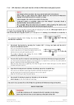
Open the front door and make sure that:
•
The
safety screens
are fixed in their position.
•
The
UPS Output Switch Q1
,
Input Circuit Breaker CB4
,
Battery Circuit Breaker
are open (Pos. O)
and the
External Maintenance Bypass Switch
is closed (Pos. I).
•
LED Alarm
is lit.
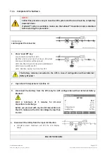
1. If not already supplied (separate utility inputs), switch-ON the utility power to the Rectifier
input.
2.
Close the UPS Output Switch Q1 (Pos. I).
LED 1 (Utility Rectifier OK)
must be lit.
The
Load
is supplied by the
Utility
through the
UPS Automatic
Bypass
and
External Maintenance Bypass (option)
.
The
Synoptic Diagram
must display the status
“
LOAD
SUPPLIED BY AUTOMATIC BYPASS
”
.
Input Circuit Breaker CB4
closes automatically.
LED 3 (Rectifier ON)
must blink.
The
Rectifier
starts up automatically, supplying the
DC circuit
, and charging the
DC capacitors
.
The
LED 3 (Rectifier ON)
stops blinking and stays ON, indicating that the DC link has reached the floating
voltage.
3. Connect the Battery to the UPS by closing (Pos. I) the Battery Circuit Breaker.
LED 4b
(Charging Battery)
should be lit indicating
Battery Charge
.
ATTENTION !
Before performing this operation, the
LED 3 (Rectifier ON)
must remain lit, thus
indicating that the DC-Link has reached floating voltage (540Vdc)!
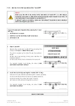
4. Transfer the Load from External Maintenance Bypass (option) to UPS Automatic Bypass.
Use the
External Maintenance Bypass panel instructions
to transfer the
Load
from the
External Maintenance
Bypass Breaker (MBB)
to the
UPS Automatic Bypass
.
After this step, the
Load
is supplied by the
Utility
through the
Automatic Bypass
.
MBB Open, MIB(s) Closed, and
“
LOAD SUPPLIED BY AUTOMATIC BYPASS
”
must display on the
Synoptic
Diagram
.
5. Insert the Inverter by pressing the “Inverter ON” ( I ) key
.
Soft-start of
Inverter
indicated with blinking
LED 5 (Inverter available)
.
At the end of Soft-start the
LED 5 (Inverter available)
remains lit.
Automatic transfer from
Automatic Bypass
to
Inverter
.
UPS output
LED
indicates
Load on Inverter
.
LED Alarm
turn Off and the
LED Operation
must be lit.
The
Synoptic Diagram
must display the status
“
LOAD
SUPPLIED BY INVERTER
”
.
END OF PROCEDURE