background image

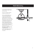
Blade Balancing Kit

The balancing kit should only be used if there is an 

unacceptable amount of fan wobble after completing 

all the steps in the user manual under “Attaching the 

Fan Blades”.

1.

Turn the fan on and set the speed control setting to

the speed at which the wobble is the greatest.

2.

Turn off the fan and allow it to come to a complete

stop. Mark the blades with masking tape number 

1-3. Select one blade and place the balance clip on it 

halfway between the blade holder and the blade tip on 

the trailing edge of the blade (fig. a) .

3.

Turn the fan on. Note whether the wobble has

increased or decreased. Turn the fan off, move the clip 

to another blade, and retest. Repeat this procedure

on all blades noting the blade on which the greatest

improvement is achieved.

4.

Adjust the clip on this blade as shown in the

n

o

it

i

s

o

p

e

h

t

d

n

if

o

t

n

a

f

e

h

t

e

t

a

r

e

p

o

d

n

a

n

o

it

a

r

t

s

u

ll

i

where the clip gives the greatest improvement

6.

If the fan wobble problem has not been corrected,

you may wish to try to improve the balancing further by 

using the balancing clip and additional weights.

5.

Clean the area on top of the blade near where the clip

is located. Install a balancing weight to the top of the 

blade along the center line (fig c).

(fig. b).

 fig. a

attach the plastic

clip on blade

fig. b

fig. c

Weight

balance

18

Содержание 20673

Страница 1: ...Hz MADE IN CHINA User Manual Customer Assistance 1 866 885 4649 re Service Team at 1 866 885 4649 re 9 00AM 5 00PM EST Monday Friday Note Installation videos for fans with GE Powerplug quick connection technology onwww gelightingandfans com can be viewed and downloaded r ...

Страница 2: ...box The wires should be spread apart with the grounded conductor and the equipment grounding conductor on one side of the outlet box and ungrounded conductor on the other side of the outlet box 12 All screws must be checked and re tightened where necessary during installation 5 CAUTION To avoid personal injury the use of gloves may be necessary while handling fan parts with sharp edges Vaulted cei...

Страница 3: ...ts each may be controlled by a separate wiring circuit 5 When replacing fuses turn off the main power rst Make sure your hands and feet are dry and place one hand behind your back to prevent electricity from making a complete circuit through your chest Touch a plug fuse only by its insulated rim 6 Remove cartridge fuses with fuse puller 7 Use tools with insulated handles and ladders made of wood o...

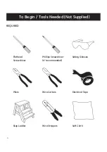
Страница 4: ...4 To Begin Tools Needed Not Supplied REQUIRED Flathead Screwdriver Pliers Step Ladder Phillips Screwdriver 4 recommended Wire Cutters Wire Strippers Safety Glasses Electrical Tape Soft Cloth ...

Страница 5: ...J 1 2 BB 2 II 1 LL 2 DD 9 1 replacement KK 1 Hardware Bag Remote Control PART DESCRIPTION Wood Screw Long Wire Connector Transmitter 1 5 Volt AAA battery Mounting Screw with lock washer Blade Screw Wood Screw Short Flat Washer Balance Kit Transmitter Holder QUANTITY FF AA DD EE LL BB II KK CC JJ FF ATTENTION Parts are not to scale NOTE 1 Extra quantity supplied for future use if needed GG HH HH GG...

Страница 6: ...ional Fasteners N O K 1 2 Collar set screw Clevis pin L 1 Cotter pin M 3 Mounting plate screw 1 Canopy trim ring I P N O LED light kit mounting screw Preassembled to metal housing Metal Housing 1 3 Preassembled to mounting bracket Preassembled to coupling of motor assembly Preassembled to coupling of downrod assembly Preassembled to coupling of downrod assembly Preassembled to mounting plate of mo...

Страница 7: ...ale 3 pin connector female Clevis pin Mounting plate screw 9 pin connector male Blade screw Metal housing LED light kit 9 pin connector female Shade LED light kit mounting screw Blade Cotter pin Collar set screw Motor assembly Neutral white wire Powerplug receptacle Flat washer Outlet box screw Plug locking pin Canopy mounting screw Mounting bracket Black wire from receiver White wire from receive...

Страница 8: ...nsulation from end of each wire if necessary Fig 1 NOTE Do NOT strip any more than 1 2 in of insulation from end of wires as this could cause a short at any time IMPORTANT Wiring must not come down and around the face of powerplug receptacle Connect GREEN BARE wire from ceiling to terminal in powerplug receptacle marked G Secure the wire by tightening the small set screw Reference the wiring confi...

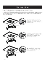
Страница 9: ...ort 15 9 kg 35 lb min DANGER A loose outlet box can cause the fan to wobble and increase the fan s potential to fall which could result in serious injury or death A BB CC 2 Install powerplug receptacle A to outlet box using the mounting screws with lock washer BB and flat washers CC provided with the outlet box Two additional mounting screws with lock washer BB and flat washers CC are provided in ...

Страница 10: ...ng or the gap is less than 1 5mm use 4mm rubber washer provided Place the washer above the powerplug receptacle as shown Fig 3 Outlet box and the ceiling with gap from 3mm to 5mm use both 4mm and 7mm rubber washers provided Place the washer above the powerplug receptacle as shown 4mmrubber washer 0 1 5mm 1 5 3mm 7mm rubber washer 4mm rubber washer 3mm 7mm rubber washer Fig 2 Outlet box and ceiling...

Страница 11: ...ket push lever on the canopy is placed in the middle between the receptacle j slots as shown in the picture Keep the lever pushed up while turning the fan to the right clockwise as shown in step 7 Loosen but do not remove the two collar set screws L from the coupling on the top of the motor assembly E Attach the 3 pin connectors from the downrod of the canopy assembly B and motor assembly E Carefu...

Страница 12: ...epeat for the remaining blades tighten all screws Tighten all the 4 canopy mounting screws K K Groove Tab K 7 FINISHING THE FAN INSTALLATION B 8 10 1 2 Make sure the tab on the mounting bracket socket is properly seated in the groove in the hanger ball downrod assembly B This will help to balance the ceiling fan WARNING Failure to properly seat the tab in the groove could cause damage to wiring Ro...

Страница 13: ...ector through the center hole on the metal housing F Raise the metal housing F up to the mounting plate position keyhole slots around the mounting plate screws O and twist clockwise Insert the mounting plate screw O that you had previously removed Tighten all screws Attach the 9 pin connectors from the LED light kit G and motor assembly Tuck the connections neatly into the LED light kit G align th...

Страница 14: ...trols the light and also controls the brightness setting Press and release the button to turn the light ON or OFF Press and hold the button to set the desired brightness the light will slowly illuminate to maximum light output and then stop when holding the button then release the button and hold it again until it reaches minimal illumination where it will automatically stop again The light button...

Страница 15: ...the instructions may cause harmful interference to radio communications However there is no guarantee that interference will not occur in a particular installation If this equipment does cause harmful interference to radio or television reception which can be determined by turning the equipment off and on the user is encouraged to try to correct the interference by one or more of the following mea...

Страница 16: ...he polarity of the batteries is correct 4 Turn on the power isolation switch to ALL fans 5 Press the Sync switch with the corner of the battery cover you can also use a small screwdriver or ballpoint pen to change the frequency settings within 30 seconds after restoring the power The lights will flash on off 3 times and remain bright then the pairing process is complete 6 Try different speed setti...

Страница 17: ...above the tip of one of the blades Measure from a point on the center of each blade to the point on the ceiling Measure this distance as n a f e h t e t a t o R e r u g i f n i n w o h s until the next blade is positioned for measurement Repeat for each blade Measurements deviation should be within 3 mm 1 8 in Run the fan for 10 minutes 17 Use the enclosed Blade Balancing Kit if the blade wobble i...

Страница 18: ...ther the wobble has increased or decreased Turn the fan off move the clip to another blade and retest Repeat this procedure on all blades noting the blade on which the greatest improvement is achieved 4 Adjust the clip on this blade as shown in the n o i t i s o p e h t d n i f o t n a f e h t e t a r e p o d n a n o i t a r t s u l l i where the clip gives the greatest improvement 6 If the fan wo...

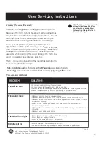
Страница 19: ...Parkway Suite 154 Alpharetta GA 30022 V1 2016 Make sure all motor housing screws are snug Make sure the screws that attach the fan blade bracket to the motor hub is tight Make sure wire nut connections are not rattling against each other on the interior wall of the switch housing Allow a 24 hour breaking in period Most noises associated with a new fan disappear during this time Make sure there is ...

Страница 20: ...9 00 a m a 5 00 p m EST de Lunes a Viernes fi Nota Videos de Instalación para ventiladores con la tecnología de instalación rápida con enchufe GE pueden ser vistos y descargados en www gelightingandfans com Manual del Usuario 1 37 m 54 pulgadas Ventilador de techo LED Morgan MODELOS 20673 20680 120V 60Hz HECHO EN CHINA Asistencia al cliente 1 866 885 4649 ...

Страница 21: ...l ventilador y otros elementos tenga cuidado al trabajar cerca del ventilador o al limpiarlo 10 No utilice agua ni detergentes al limpiar el ventilador o las aspas Un trapo seco o un paño ligeramente humedecido será adecuado para la mayor parte de limpieza 11 Después de realizar las conexiones eléctricas los conductores empalmados se deben voltear hacia arriba y empujarse con cuidado dentro de la ...

Страница 22: ...5 Al sustituir los fusibles apague primero el cable de corriente Asegúrese de que sus manos y sus pies estén secos y coloque una mano detrás de la espalda para evitar que la electricidad haga un circuito cerrado completo a través de su pecho Toque un fusible del enchufe solamente por medio de su borde aislado 6 Retire los fusibles de cartucho con un extractor de fusibles 7 Utilice herramientas con...

Страница 23: ... Necesarias No suministradas NECESARIO Destornillador de Cabeza Plana Alicates Escalera Destornillador de Estrella o Phillips 4 recomendado Cortadores de Cable Pelacables Gafas de Seguridad Cinta Eléctrica Paño Suave ...

Страница 24: ...o de montaje con arandela de seguridad Tornillo del aspa Tornillo de madera Corto Arandela plana Kit de balanceo Soporte de transmisor GG AA DD EE JJ BB II CC FF Desempaque con cuidado e identifique cada una de las piezas para que se asegure de que tiene todo listo para la instalación Coloque todas las piezas en una superficie limpia y plana como una mesa o alfombra Revise para asegurarse de que t...

Страница 25: ... de metal Cubierta de metal 1 3 Preinstalado al soporte de montaje Preinstalado al acoplamiento del conjunto del motor Preinstalado al conjunto de varilla del dosel Preinstalado al conjunto de varilla del dosel Preinstalado al soporte de montaje del conjunto del motor Desempaque con cuidado e identi que cada una de las piezas para que se asegure de que tiene todo listo para la instalación Coloque ...

Страница 26: ... del plato de montaje Conector de 9 presillas macho Tornillo del aspa Cubierta de metal Juego de luz LED Conector de 9 presillas hembra Campana Tornillo de Montaje del Juego de Luz Chaveta Tornillo del collar Conjunto del motor Cable blanco neutral Receptáculo del enchufe eléctrico Arandela plana Tornillo de la caja electrica Pasador de bloqueo Tornillo de montaje del dosel Soporte de montaje Cabl...

Страница 27: ...gure el cable apretando el pequeño tornillo que está en el costado Fig 2 Fig 1 Receptáculo del enchufe eléctrico cable blanco cable negro cable negro G W L1 Fig 3 L 1 ground b l a c k L1 W G cable blanco cable verde desnudo w h i t e L2 r e d VISTA CERCANA de los TERMINALES en el Receptáculo del enchufe eléctrico Refiérase al diagrama de debajo de la configuración de los cables para otras opciones...

Страница 28: ...les conectados juntos adicione un cable guía extensor e inserte este cable guía extensor en el terminal Un solo cable deberá ser introducido en el terminal ATENCION Para prevenir un posible corto circuito asegúrese que el flujo eléctrico esté apagado en el panel principal de la caja de fusibles antes de realizar el cableado ATENCION No use un soporte de montaje existente en la caja eléctrica reemp...

Страница 29: ...m use una arandela de goma de 4mm provista Coloque la arandela sobre el receptáculo del enchufe eléctrico como se muestra Fig 2 La caja eléctrica está a un espacio de más de 1 5mm pero de menos de 3mm use la arandela de goma de 7mm provista Coloque la arandela sobre el receptáculo del enchufe eléctrico como se muestra Fig 3 La caja eléctrica está a un espacio de entre 3mm a 5mm del techo use ambas...

Страница 30: ...cuidadoso de no atascar la chaveta M contra los cables dentro del tubo Inserte el pasador de horquilla N a través del orificio extremo de la chaveta M hasta que quede ajustada en cerca del la posición de bloqueo Apriete los dos tornillos L en la parte de arriba del collar del motor firmememte hasta que queden seguros Para instalar el ventilador levante la carcasa del ventilador montado hasta el re...

Страница 31: ...junto de varilla B Esto ayuda a balancear el ventilador ADVERTENCIA Fallo de colocar apropiadamente la lengüeta en la ranura puede causar daños al cableado Nota Gire el dosel a la derecha siga girando el dosel hasta que los tornillos K encajen en las ranuras j del receptáculo Gire el dosel a la derecha sentido horario siga girando el dosel hasta que los tornillos K encajen en las ranuras j del rec...

Страница 32: ...icios alrededor de los tornillos del plato de montaje O y gírelo a favor de las manecillas del reloj Inserte el tornillo del plato de montaje O que había retirado previamente Apriete todos los tornillos 2 conector de 9 presillas G P F O F Adjunte el conector de 9 presillas del juego de luz LED G y el conjunto del motor Introduzca las conexiones cuidadosamente dentro del juego de luz LED G alinee l...

Страница 33: ... Verifique el interruptor dip O y I Para este ventilador el interruptor dip deberá estar en la posición I para que permita regular la luz Coloque el interruptor dip en la posición O para desactivar la función de regulación si no desea esta opción Paso 4 Cierre el compartimento de la batería y vea el diagrama de abajo para las funciones diponibles de cada botón del control remoto Paso 5 Selecione e...

Страница 34: ...uientes 2 1 Este artículo no debe causar interferencia dañina y 2 Este artículo deberá aceptar cualquier interferencia recibida incluyendo interferencia que pueda causar un funcionamiento no deseado CUIDADO Cualquier cambio o modificación no aprobada por el equipo de regulaciones podrá cancelar la autoridad del usuario de operar este artículo Nota Este artículo ha sido probado y se determino que c...

Страница 35: ...resione el interruptor de sincronización Sync con la esquina de la cubierta de la batería también puede usar un bolígrafo o un destornillador pequeño para cambiar la frequencia de las configuraciones dentro de 30 segundos luego de reestablecer la electricidad Las luces se pondrán intermitentes 3 veces y luego permanecerán encendidas cuando el proceso de sincronización ha finalizado 6 Intente difer...

Страница 36: ...ando un punto en el techo por encima de la punta de una de las aspas Mida desde un punto en el centro de cada aspa hasta el punto en el techo Mida esta distancia tal como se muestra en la gura Gire el ventilador hasta que la siguiente aspa esté situada para la medición Repita el procedimiento para cada aspa La desviación de la medición debe estar dentro de 1 8 3 mm Ponga a funcionar el ventilador ...

Страница 37: ...edimiento en todas las palas observando en cuál se produce la mayor mejora 4 Mueva la grapa hacia adentro y hacia afuera sobre esta pala haciendo funcionar el ventilador hasta hallar la posición en la cual la grapa produzca la mayor mejora fig b 5 Retire la grapa e instale una pesa de balanceo en la parte superior de la pala sobre la linea central cerca del punto donde estaba colocada la grapa fig...

Страница 38: ...casquillos no choquen entre sí o que contra las paredes internas de la caja del interruptor Deje funcionar durante un periodo de 24 horas La mayoría de los ruidos asociados a un ventilador nuevo suelen desaparecer después de este período Verifique también que la lámpara esté bien ajustada Cerciórese de que haya una entre el techo y la roseta Esta no debe tocar el techo Asegúrese que la caja eléctr...

Отзывы: