background image


I

NSTALLING THE 

NX-216Z8 


The first thing that must be decided is the starting zone of this particular zone expander. The 

starting zone must be on a boundary of eight (8) zones. The eight (8) zones then move out from 

this starting position. There are stick-on zone labels to indicate the zone numbers that you 

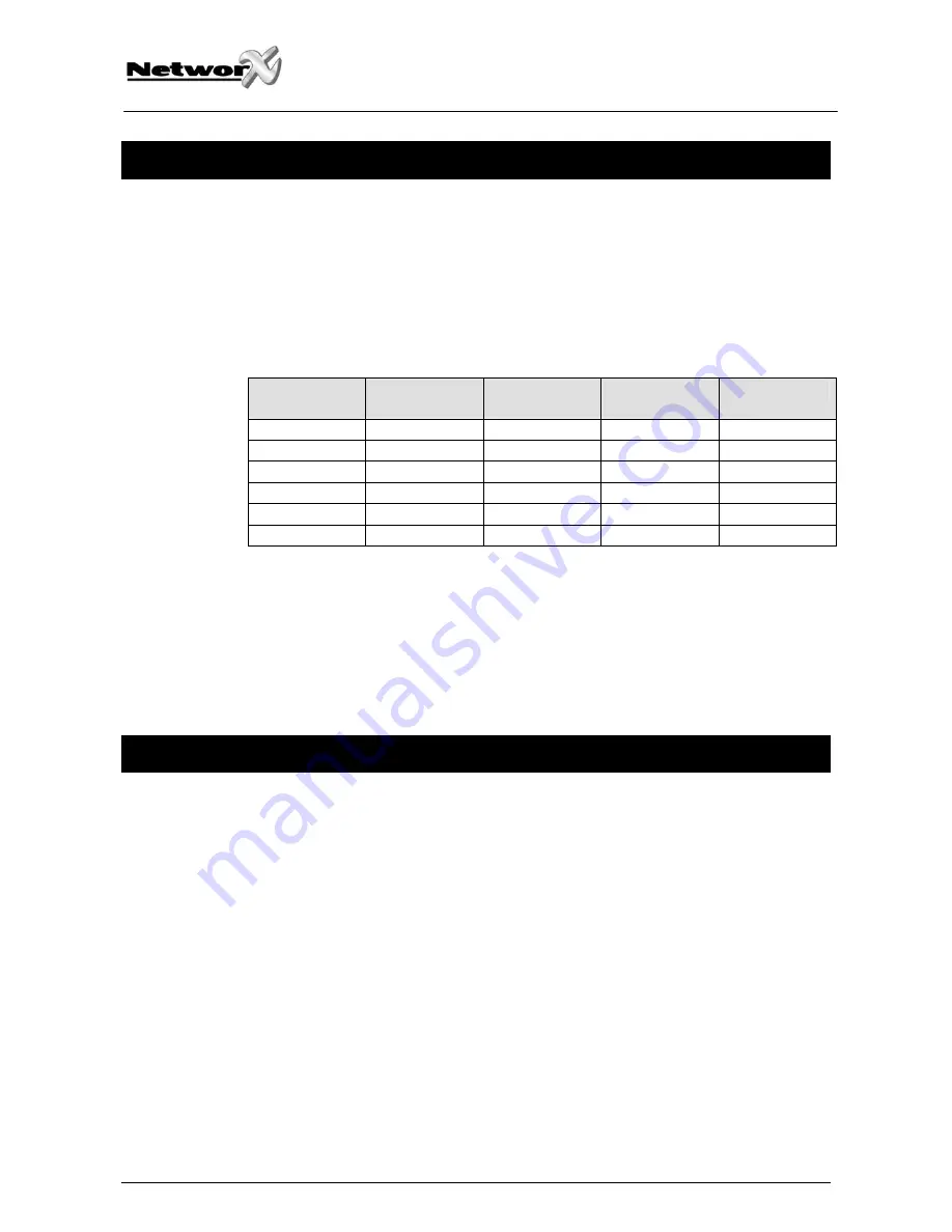
select. To set the starting zone, set the DIP switch according to the table below:  

Note: the position of all switches is only updated when the NX-216Z8 is powered up. Before 

you change the position of these switches you must power down the expander.  


Starting zone 

number 

DIP switch 1 

DIP switch 2 

DIP switch 3 

Module number 

9  OFF OFF OFF  22 
9 ON OFF 

OFF 23 

17 OFF ON OFF 16 
25 ON ON OFF 17 
33 OFF OFF ON  18 
41 ON OFF ON 19 


DIP switch 4: DIP switch 4 is used to disable the second block of eight (8) zones on this zone 

expander. This can be done if only an eight (8) zone expander is required in a particular 

expander location. In this case, up to 5 expanders can be added to the system creating a total 

of 48 zones. To disable the second group of eight (8) zones on this expander, turn DIP switch 4 

on.  


E

NROLLING THE 

NX-216Z8

 EXPANDER


For supervision purposes, the presence of all keypads, zone expanders, wireless receivers, and 

any other modules connected to the data terminal can automatically be found and stored in 

the NX-8’s memory. This allows the control panel to supervise these modules. To enroll the 

modules, enter the program mode for the NX-8 control panel as described in the paragraph of 

this manual. If necessary, go on to program the rest of the control panel and the devices. 

When you exit from program mode, the control panel will automatically enroll the devices. The 

enrolling process takes about 12 seconds, during which time a “Service” indication will be 

displayed. If a module has been enrolled but it is not detected by the control, the “Service” 

indication (LED or LCD screen) will be displayed. 

NX-216Z8 Installation manual 

Page 4 

 26/06/06 

Содержание NetworX NX-216Z8

Страница 1: ...GE Security NetworX TM Series NX 216Z8 Zone Expander Installation manual g imagination at work ...

Страница 2: ...THE LED KEYPAD 5 ENTERING THE PROGRAM MODE 5 SELECTING THE MODULE TO PROGRAM 5 PROGRAMMING A LOCATION 5 EXITING A LOCATION 5 EXITING THE PROGRAM MODE 6 PROGRAMMING THE NX 216Z8 VIA THE LCD KEYPAD 6 PROGRAMMING DATA 7 ZONE CONFIGURATIONS AND PARTITION SELECTION 8 TERMINAL DESCRIPTION 8 NX 216Z8 PRINT LAYOUT 9 TECHNICAL SPECIFICATIONS 9 CE DECLARATION 10 NX 216Z8 Installation manual Page 2 26 06 06 ...

Страница 3: ...etworX control panel with a maximum zone count of 48 zones Each expander has an optional tamper switch and power isolator making it ideal for use in a remote location ORDERING INFORMATION For detailed ordering information and part numbers please refer to the EMEA Distribution price list of the Caddx product range NX 216Z8 Installation manual Page 3 26 06 06 ...

Страница 4: ...ander is required in a particular expander location In this case up to 5 expanders can be added to the system creating a total of 48 zones To disable the second group of eight 8 zones on this expander turn DIP switch 4 on ENROLLING THE NX 216Z8 EXPANDER For supervision purposes the presence of all keypads zone expanders wireless receivers and any other modules connected to the data terminal can au...

Страница 5: ...he Ready LED will illuminate and the zone LED s will show the binary data for the first segment of this location While entering new data the Ready LED will begin flashing to indicate a data change in process The flashing will continue until the new data is stored by pressing the key Upon pressing the key the keypad will advance to the next segment and display its data This procedure is repeated un...

Страница 6: ...programming these devices is the same as for the control panel except the locations will be for the module selected Note the timeout for the program mode is 15 minutes Programming the NX 216Z8 via the LCD keypad All steps required for programming are the same as the aforementioned LED keypad The LCD keypad display will prompt you for the data required While in the programming mode and not in a loc...

Страница 7: ...d sounder will emit a triple beep indicating an error and remain in that segment awaiting a valid entry Remark on the LCD keypad the number in the location will be displayed For locations with a maximum of 15 the hexadecimal equivalent will be displayed in parenthesis Example 11 B or 14 E FEATURE SELECTION DATA Feature selection data will display the current condition on or off of eight features a...

Страница 8: ...panel see the wiring diagram for wire specifications TAM Connect as shown below If not used connect to a COM terminal AUX Can be used to power devices directly from the NX 216Z8 Power is coming from the control panel therefore the current draw of these devices must be added to the total current draw of the NX 216Z8 This output is current limited to 100 mA Z9 Connect to one side of zone 9 loop Conn...

Страница 9: ... Vdc Auxiliary power output supplied from NX 8 control panel or NX 320 power supply max current consumption 100 mA restricted by NX 216Z8 Current consumption typical 5 mA Loop resistance 300 Ohm maximum Loop response selectable 50 ms or 500 ms Operating temperature 0 50 C Dimensions LxWxH 153 x 54 x 18 mm Weight 58 g NX 216Z8 Installation manual Page 9 26 06 06 ...

Страница 10: ...CE DECLARATION NX 216Z8 Installation manual Page 10 26 06 06 ...

Страница 11: ...A bvba COPYRIGHT 2004 GE Security EMEA bvba All rights reserved GE Security EMEA bvba grants the right to reprint this manual for internal use only GE Security EMEA bvba reserves the right to change information without notice NX 216Z8 Installation manual Page 11 26 06 06 ...

Отзывы: