5-54
F35 Multiple Feeder Protection System
GE Multilin
5.2 PRODUCT SETUP
5 SETTINGS
5
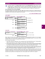
An example user display setup and result is shown below:
5.2.17 DIRECT INPUTS/OUTPUTS
a) MAIN MENU
PATH: SETTINGS
Ö
PRODUCT SETUP
ÖØ
DIRECT I/O
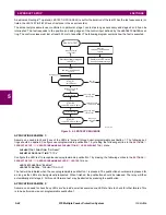
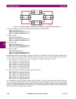
Direct inputs and outputs are intended for exchange of status information (inputs and outputs) between UR-series relays
connected directly via type 7 digital communications cards. The mechanism is very similar to IEC 61850 GSSE, except that
communications takes place over a non-switchable isolated network and is optimized for speed. On type 7 cards that sup-
port two channels, direct output messages are sent from both channels simultaneously. This effectively sends direct output
USER DISPLAY 1
DISP 1 TOP LINE:
Current X ~
A
Shows user-defined text with first Tilde marker.
MESSAGE
DISP 1 BOTTOM LINE:
Current Y ~
A
Shows user-defined text with second Tilde marker.
MESSAGE
DISP 1 ITEM 1:
6016
Shows decimal form of user-selected Modbus Register
Address, corresponding to first Tilde marker.
MESSAGE
DISP 1 ITEM 2:
6357
Shows decimal form of user-selected Modbus
Register Address, corresponding to 2nd Tilde marker.
MESSAGE
DISP 1 ITEM 3:
0
This item is not being used - there is no corresponding
Tilde marker in Top or Bottom lines.
MESSAGE
DISP 1 ITEM 4:
0
This item is not being used - there is no corresponding
Tilde marker in Top or Bottom lines.
MESSAGE
DISP 1 ITEM 5:
0
This item is not being used - there is no corresponding
Tilde marker in Top or Bottom lines.
USER
DISPLAYS
→
Current X 0.850 A
Current Y 0.327 A
Shows the resultant display content.
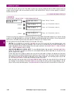
DIRECT I/O
DIRECT OUTPUT
DEVICE ID: 1
Range: 1 to 16
MESSAGE
DIRECT I/O CH1 RING
CONFIGURATION: Yes
Range: Yes, No
MESSAGE
DIRECT I/O CH2 RING
CONFIGURATION: Yes
Range: Yes, No
MESSAGE
DIRECT I/O DATA
RATE: 64 kbps
Range: 64 kbps, 128 kbps
MESSAGE
DIRECT I/O CHANNEL
CROSSOVER: Disabled
Range: Disabled, Enabled
MESSAGE
CRC ALARM CH1
MESSAGE
CRC ALARM CH2
MESSAGE
UNRETURNED
MESSAGES ALARM CH1
MESSAGE
UNRETURNED
MESSAGES ALARM CH2
Содержание F35
Страница 2: ......
Страница 4: ......
Страница 30: ...1 20 F35 Multiple Feeder Protection System GE Multilin 1 5 USING THE RELAY 1 GETTING STARTED 1 ...
Страница 122: ...4 30 F35 Multiple Feeder Protection System GE Multilin 4 3 FACEPLATE INTERFACE 4 HUMAN INTERFACES 4 ...
Страница 296: ...5 174 F35 Multiple Feeder Protection System GE Multilin 5 9 TESTING 5 SETTINGS 5 ...
Страница 328: ...7 8 F35 Multiple Feeder Protection System GE Multilin 7 2 TARGETS 7 COMMANDS AND TARGETS 7 ...
Страница 332: ...8 4 F35 Multiple Feeder Protection System GE Multilin 8 1 FAULT LOCATOR 8 THEORY OF OPERATION 8 ...
Страница 350: ...A 16 F35 Multiple Feeder Protection System GE Multilin A 1 PARAMETER LIST APPENDIXA A ...
Страница 422: ...B 72 F35 Multiple Feeder Protection System GE Multilin B 4 MEMORY MAPPING APPENDIXB B ...
Страница 460: ...D 10 F35 Multiple Feeder Protection System GE Multilin D 1 IEC 60870 5 104 PROTOCOL APPENDIXD D ...
Страница 472: ...E 12 F35 Multiple Feeder Protection System GE Multilin E 2 DNP POINT LISTS APPENDIXE E ...


